Banks Power Cummins Motorhomes: (Diesel ’93 - 98 B5.9L & C8.3L) PowerPack & Stinger systems w_Twin Ram Manifold 5.9L, 190-210-230-hp rated User Manual
Page 5
Tap the drilled hole with a
1
⁄
4
npT pipe tap.
check the thread depth as you tap by
periodically removing the tap and screwing the
probe fitting (supplied in pyrometer kit) into the
tapped hole. The probe should thread in 3 to 3
1
⁄
2
turns hand tight. Do not install the probe in place
at this time.
remove as many loose chips as possible
from the exhaust manifold. a shop vacuum,
small brush, or fingers will help. now remove the
rag using a welding rod or coat hanger bent into a
hook.
CAUTION! Make sure rags are removed from
exhaust manifold prior to reinstalling turbine
housing!
install the probe in the manifold. anti-seize
on the threads is recommended.
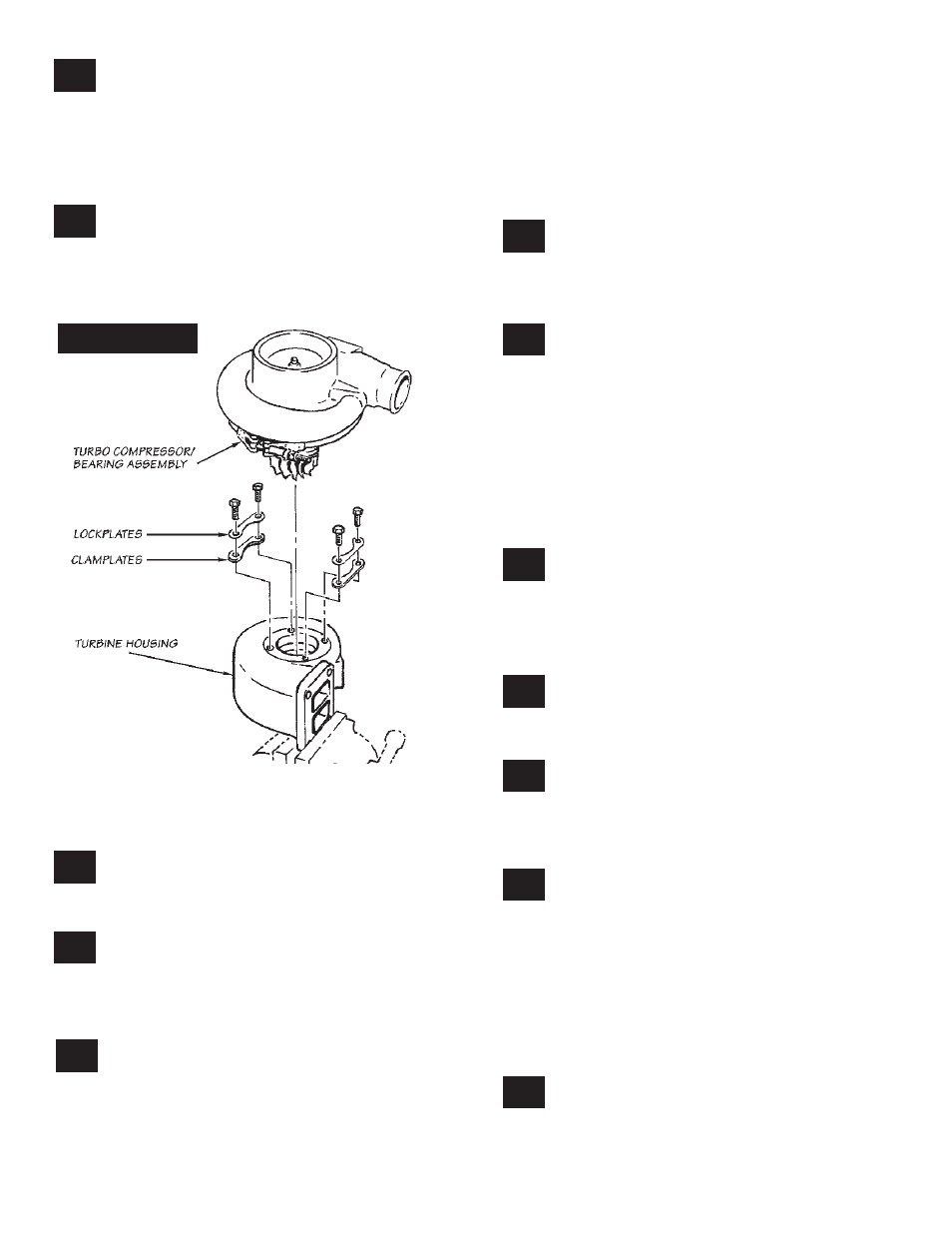
TURBOCHARGER DISASSEMBLY AND REASSEMBLY:
clamp the turbine inlet flange of the
turbocharger in a bench vise. loosen the
four bolts, attaching the turbine housing to the
center bearing section of the turbocharger. (
see
Figure 2
)
remove the bolts, lockplates, and clamp
plates. carefully remove the center bearing
and compressor assembly from the cast iron
turbine housing. if the turbocharger has been in
service for some time, rust and carbon may prevent
the center bearing and compressor assembly from
easily separating from the turbine housing. if light
hammer blows, penetrating oil or heat will not
free the compressor assembly from the turbine
housing, the clamp bolt adjacent to the turbo oil
inlet connection may be backed out so as to push
against the bearing casting and separate the two
components. remove any loose rust or carbon
from the bearing housing that might prevent proper
engagement into the new turbine housing.
install the center bearing and compressor
assembly into the new turbine housing
supplied. apply a dab of anti-seize compound to the
bolts, then install bolts, clamp plates, and lock plates
finger tight to allow for final positioning.
remove the exhaust outlet adapter from
the rear of the turbine housing. clamp the
exhaust inlet flange of the new turbine housing
in a bench vise. using the new gasket provided
install the turbo exhaust outlet adapter casting to
the turbine housing with five 8mm x 20mm metric
hex bolts. apply a dab of anti-seize compound to
the bolts, then torque the bolts to 11.3n-m (100
in-lbs.). Make sure the turbine inlet flange does
not rotate in the vise while torquing.
TURBOCHARGER INSTALLATION
install a new turbo exhaust inlet gasket
provided and apply a dab of anti-seize
compound to the four turbo mounting studs.
install the turbocharger on the exhaust manifold.
Tighten the turbocharger mounting nuts to 32n-m
(24 ft.lbs.) torque.
align the compressor outlet with the
intercooler hose adapter and tighten the
clamp. Tighten the turbine housing clamp plate
bolts to 11.3n-m (100 in-lb.) torque.
spin the turbocharger shaft to make sure it
turns freely. if not, loosen the turbine clamp
plate bolts and check for misalignment between the
turbine housing and turbocharger center section.
retighten bolts and check again.
use the new gasket provided to connect the
turbocharger oil drain tube to the turbocharger.
Make sure the turbocharger oil drain flange is clean
and free of any old gasket material. Tighten the drain
flange bolts to 24n-m (18 ft.lbs.) torque. nOTe: if the
bolts encounter excessive resistance prior to seating
against the flange, check for paint build up in the
threads of the turbo bearing housing. The threads
may need to be chased with an 8mm x 1.25 metric
tap.
reconnect and tighten the turbo oil supply
hose.
16.
17.
18.
19.
20.
21.
22.
15.
11.
12.
13.
14.
p.n. 96385
5
Figure 2