Banks Power Cummins Motorhomes: (Diesel ’93 - 98 B5.9L & C8.3L) PowerPack & Stinger systems w_Twin Ram Manifold 5.9L, 190-210-230-hp rated User Manual
Page 6
install the air inlet tube (from the air cleaner
housing) and the turbo exhaust pipe onto
the turbocharger. reattach the wastegate actuator
boost line using a crimp lock clamp provided.
GAUGE INSTALLATION
choose a suitable location under the
lower edge of the dash panel for mounting
the instrument panel provided where it can be
conveniently viewed by the driver.
Note: Molded instrument consoles for top-
of-dash mounting and additional gauges are
available through Gale Banks engineering.
using the panel as a template, drill two
3
⁄
16
”
diameter holes in the dash and mount the
panel with two no. 10 x
1
⁄
2
” machine screws, nuts
and star washers provided.
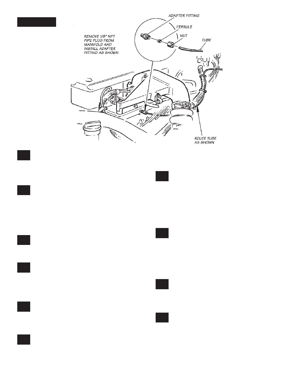
locate and remove the
1
⁄
8
” npT pipe plug
on the driver’s side of the intake manifold
as shown in Figure 3. install the
1
⁄
8
” npT male x
1
⁄
8
” compression tube adapter at this location. use
Teflon tape or sealant on the pipe thread end of
the adapter fitting.
install one end of the
1
⁄
8
” diameter plastic
tube provided in the nut and ferrule adapter
fitting and tighten the nut. check that the plastic
tube cannot be pulled out of the ferrule, but do not
over-tighten the nut.
install the boost gauge in the gauge panel
using the clamps and thumb nuts provided.
install the
1
⁄
8
” npT female x
1
⁄
8
” compression tube
adapter fitting onto the connection at the back of
the gauge. use Teflon tape or sealant on the male
threads of the gauge nipple. use sealant sparingly,
and do not allow any sealant to cover the small
pin-sized hole in the end of the gauge nipple.
route the plastic tube along one framerail
of the coach. Find an opening in the forward
bulkhead to route the tube into the driver’s
compartment. it may be necessary to drill a
3
⁄
8
”
hole. route the tube to the gauge then cut the
tube to length. insert the tube into the nut and
ferrule on the adapter fitting at the gauge, then
tighten the nut against the tube and ferrule. Do
not overtighten.
uncoil the pyrometer 4-pin connector gauge
harness. as a precaution to improper gauge
function, re-crimp the ring terminals on the ends of
the wires. connect the ring terminals to the probe
with the supplied screws. attach the YellOW & red
ring terminals from the pyrometer 4-pin connector
gauge harness to the Yellow & red probe ring
terminals, respectively.
The wires are different lengths and color
coded to prevent cross connecting. Make
sure that the screws are tight. slide the heat shrink
tubing over the connections and apply heat to the
tubing with a heat gun or other heat source.
route the gauge harness along the same
path as the boost hose. coil any excess
length and secure it with tie wraps. DO NOT
cut the harness to shorten it. The pyrometer
is calibrated to operate with the predetermined
length provided.
29.
30.
31.
32.
23.
24.
25.
26.
27.
28.
Figure 3
6
p.n. 96385