VANCO VPW-280754 User Manual
Page 14
www.vanco1.com
888.769.4156
14
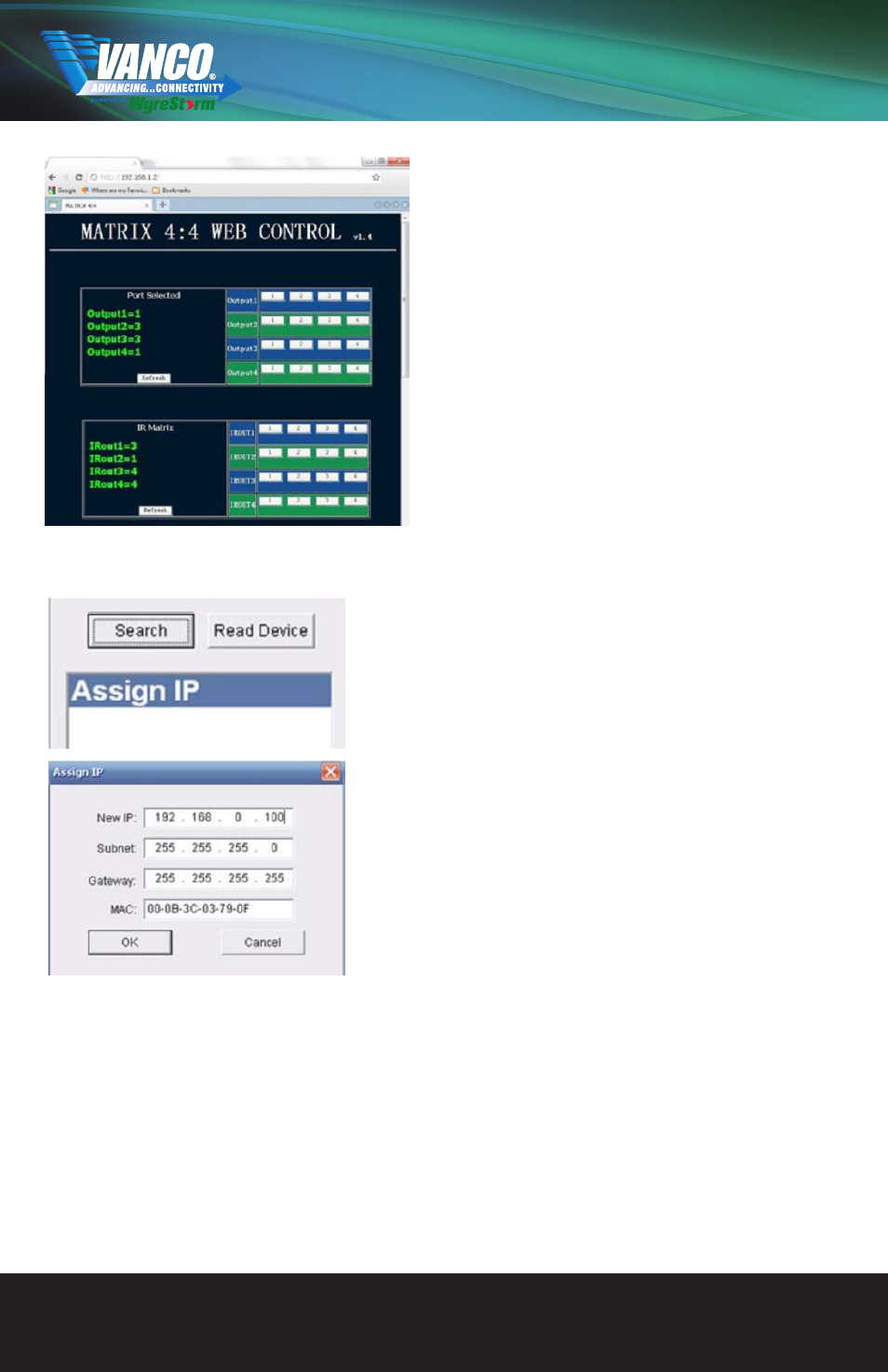
A The layout of the NET CTL controller screen includes an
upper section to allocate input sources to output with the
selection displayed on the left hand side.
Operation is the same as COM CTL – Inputs buttons 1-4
can be clicked to be selected per Output port.
Press the “REFRESH” button to update your chosen
matrix settings into the left hand display and your
selection to take effect.
B The lower section of the NET CTL controller screen
is dedicated to IR matrix settings as per the COM CTL
function 05 in the previous section. Making sure IR HEX
codes have been correctly input into the Matrix, select
the IR TX ports allocated to specific inouts/outputs to
control devices remotely over the network.
Assign IP
If ‘Assign IP’ is displayed in the dialog box, the matrix has
encountered a problem detecting an IP address and manual
input of information is required. In such instances, double
click ‘Assign IP’ or right click and choose Assign IP from the
dropdown menu to add details as required.
Click “OK” to assign the new IP address to the system and
you will return to the previous screen or “CANCEL” to return
without changes taking effect.
Now click “SEARCH” for the Matrix to detect the new IP
address, which will appear in the dialog box. Finally click
“READ DEVICE” to confirm IP settings.
ATTENTION This ‘Assign IP’ process differs from the COM
CTL ‘IP Set’ function. ‘Set IP’ in COMCTL saves/reads the
IP address in flash and sets it as static IP. ‘Assign IP’ is
only used when the system fails to obtain an IP address
automatically and is NOT saved in flash.