Operation – Velleman PS230210 User Manual
Page 3
PS230210
01.07.2009
©Velleman nv
3
3. Operation
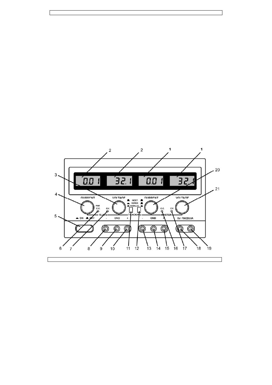
Controls and Description of the Front Panel
(1)
LCD: indicates the current value and the output voltage of the master.
(2)
LCD: indicates the current value and the output voltage of the slave.
(3)
Slave C.V.-adjustment: rotary switch to adjust the output voltage of the slave.
(4)
Slave C.C.-adjustment: rotary switch to adjust the output current of the slave (to determine the
current-limiting point)
(5)
Power switch: push button used to activate/deactivate the device. Either the C.V.- or the C.C.-
indicator is lit when the device is activated.
(6)
C.C.-mode indicator of the slave output or indicator for parallel connection: this indicator is lit when
the slave output is in the C.C.-mode or when the two adjustable outputs are connected in parallel.
(7)
C.V.-mode indicator of the slave output: this indicator is lit when the slave output is in the C.V.-
mode.
(8)
Negative binding post of the slave output: the negative pole of the output voltage is connected to
the negative terminal of the load being tested.
(9)
Earthing connection of the housing: the housing is grounded.
(10)
Positive binding post of the slave output: the positive pole of the output voltage is connected to the
positive terminal of the load being tested.
(11/12)
Control switches used to select independent operation, operation in parallel or in series.
(13)
Negative binding post of the master output: the negative pole of the output voltage is connected to
the negative terminal of the load being tested.
(14)
Earthing connection of the housing: the housing is grounded.
(15)
Positive binding post of the master output: the positive pole of the output voltage is connected to
the positive terminal of the load being tested.
(16)
Master output C.C.-indicator: this indicator is lit when the master output is in the C.C.-mode.
(17)
Master output C.V.-indicator: this indicator is lit when the master output is in the C.V.-mode.
(18)
Negative binding post of the fixed 5VDC-output: the negative pole of the output voltage is
connected to the negative terminal of the load being tested.
(19)
Positive binding post of the fixed 5VDC-output: the positive pole of the output voltage is connected
to the positive terminal of the load being tested.
(20)
Master output C.C.-adjustment: rotary switch used to adjust the current value of the master output
(adjustment of the current-limiting point).
(21)
Master output C.V.-adjustment: rotary switch used to adjust the voltage value of the master output.