Nx-s series cib module, 3ø converter + 3ø inverter + brake), Features: £ low drive power £ low v – C&H Technology CM100MXA-24S User Manual
Page 2: 100 ampere cib power module
Powerex, Inc., 173 Pavilion Lane, Youngwood, Pennsylvania 15697 (724) 925-7272
www.pwrx.com
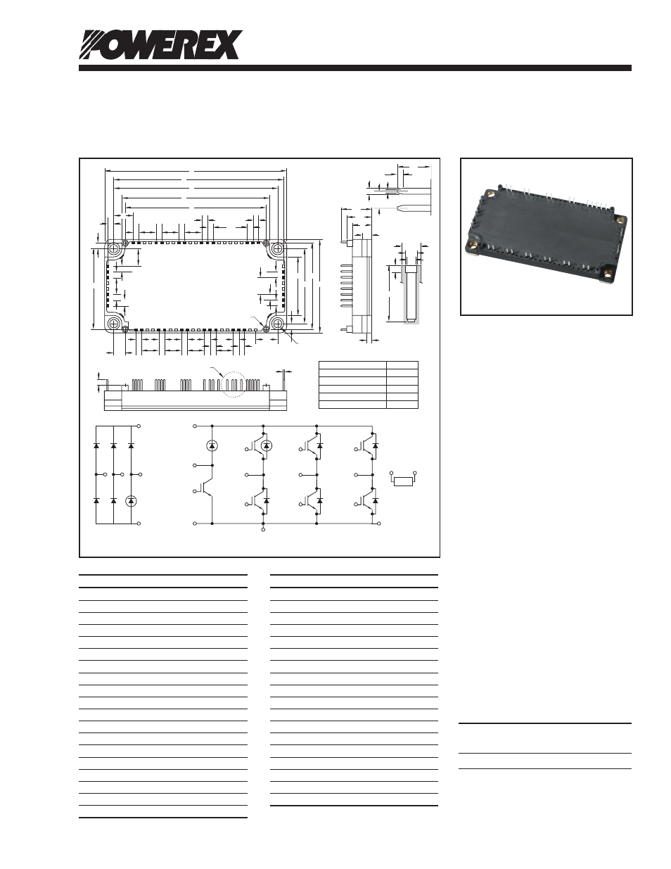
NX-S Series CIB Module
(3Ø Converter + 3Ø Inverter + Brake)
100 Amperes/1200 Volts
CM100MXA-24S
1
05/11 Rev. 2
Description:
CIBs are low profile and thermally
efficient. Each module consists of
a three-phase diode converter sec-
tion, a three-phase inverter section
and a brake circuit. A thermistor is
included in the package for sens-
ing the baseplate temperature. 6th
Generation CSTBT chips yield low
loss.
Features:
£
Low Drive Power
£
Low V
CE(sat)
£
Discrete Super-Fast Recovery
Free-Wheel Diode
£
Isolated Baseplate for Easy
Heat Sinking
Applications:
£
AC Motor Control
£
Motion/Servo Control
£
Photovoltaic/Fuel Cell
Ordering Information:
Example: Select the complete
module number you desire from
the table below -i.e.
CM100MXA-24S is a 1200V
(V
CES
), 100 Ampere CIB Power
Module.
Type
Current Rating
V
CES
Amperes
Volts (x 50)
CM 100 24
Outline Drawing and Circuit Diagram
P1(48-49)
T
(9-10)
P(54-56)
N(59-61)
ConvDi
S
(5-6)
R
(1-2)
GWN(31)
E(32)
GWP(23)
GVN(33)
GVP(18)
FWDi
GUN(40)
E*(39)
*Use both two terminals (R/S/T/P/N/P1/B/N1/U/V/W)
for the external connection.
GUP(13)
ClampDi
U(14-15)
B(52-53)
V(19-20)
W(24-25)
GB(41)
N1(44-45)
TH
1
(29)
TH
2
(28)
NTC
DETAIL "B"
A
AA
J
P
D
E
F
K
K
M
K
K
K
G
K
K
L
L
L
H
AG
K
AH
AK
AJ
Z
C
AB
R
B
AL
Y
K
K
L
N (4 PLACES)
AC
K
K
K
K
K
K
K
T
AD
W
X
L
K
K
K
K
L
L
L
L
AE
AF
V
AM
U
AN
K
Q
S
DETAIL "B"
DETAIL "A"
DETAIL "A"
1
2
3 4 5
6
7 8
9 10 11 12 13 14 15 16 17 18 19 20 21 22
53
54
55
56
57
58
59
60
61
30
29
28
27
26
25
24
23
52 51 50 49 48 47 46 45 44 43 42 41 40 39 38 37 36 35 34 33 32 31
Tolerance Otherwise Specified (mm)
The tolerance of size between
terminals is assumed to ±0.4
Division of Dimension Tolerance
0.5 to 3
±0.2
over
3 to 6
±0.3
over
6 to 30
±0.5
over 30 to 120
±0.8
over 120 to 400
±1.2
Dimensions
Inches
Millimeters
A
4.79
121.7
B
2.44
62.0
C
0.51
13.0
D
4.49
114.05
E
4.33±0.02 110.0±0.5
F
3.89
99.0
G
3.72
94.5
H
0.16
4.06
J
0.51
13.09
K
0.15
3.81
L
0.45
11.43
M
0.9
22.86
N
0.22 Dia.
5.5 Dia.
P
2.13
54.2
Q
1.53
39.0
R
1.97±0.02 50.0±0.5
S
2.26
57.5
T
0.30
7.75
U
0.102 Dia.
2.6 Dia.
Dimensions
Inches
Millimeters
V
0.088 Dia.
2.25 Dia.
W
0.46
11.66
X
0.16
4.2
Y
0.59
15.0
Z
0.27
7.0
AA
0.81
20.5
AB
0.67
17.0
AC
0.12
3.0
AD
0.14
3.5
AE
0.03
0.8
AF
0.15
3.75
AG
0.05
1.15
AH
0.025
0.65
AJ
0.29
7.4
AK
0.05
1.2
AL
0.49
12.5
AM
0.12
3.0
AN
0.17 Dia.
4.3 Dia.