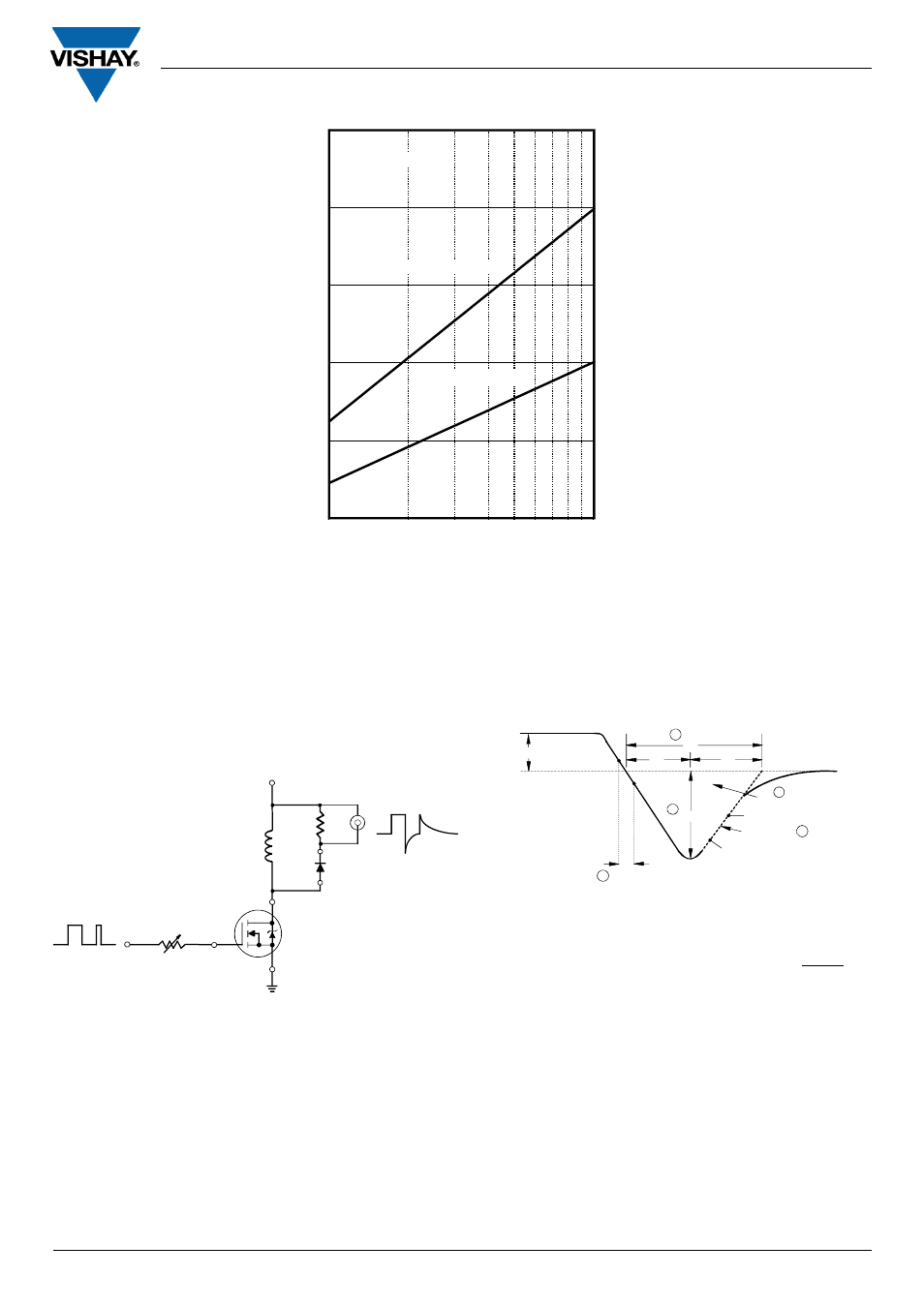
Vishay semiconductor italy, Irr ( a ) di, Dt (a/μs ) fig. 9 - typical stored current vs. di – C&H Technology UFL200FA60P User Manual
Page 6
UFL200FA60P
Vishay Semiconductor Italy
www.vishay.com
5
Document Number: I27322
Revision 30-Oct-07
100
1000
0
10
20
30
40
50
If = 50A, 125°C
If = 50A, 25°C
Vr = 200V
Irr ( A )
di
F
/dt (A/μs )
Fig. 9 - Typical Stored Current vs. di
F
/dt
Fig. 11 - Reverse Recovery Waveform and Defini-
tions
Fig. 10 - Reverse Recovery Parameter Test
Circuit
IRFP250
D.U.T.
L = 70µH
V = 200V
R
0.01 Ω
G
D
S
dif/dt
ADJUST
4. Q
rr
- Area under curve defined by
t
rr
and I
RRM
5. di
(rec) M
/ dt - Peak rate of change
of current during t
b
portion of t
rr
1. di
F
/dt - Rate of change of current through
zero crossing
2. I
RRM
- Peak reverse recovery current
3. t
rr
- Reverse recovery time measured from
zero crossing point of negative going I
F
to
point where a line passing through 0.75 I
RRM
and 0.50 I
RRM
extrapolated to zero current
Q
rr =
t rr x I
RRM
2
t
a
t
b
t
rr
Q
rr
I
F
I
RRM
I
RRM
0.5
di(rec)M/dt
0.75 I
RRM
5
4
3
2
0
1
di /dt
f
- TDK4_ _3302 (5 pages)
- CM75TL-12NF (5 pages)
- PM600HSA120 (5 pages)
- GLI......A (4 pages)
- PM600DVA060 (5 pages)
- VSKDS408-060 (10 pages)
- G200 (5 pages)
- VS30ASR..N Series (2 pages)
- LPS1100 (6 pages)
- PM50CL1B120 (6 pages)
- CPS (3 pages)
- PM200DSA060 (7 pages)
- RM400HA-34S (5 pages)
- VS-GB100TH120U (8 pages)
- PP300B120 (8 pages)
- PP400B060 (8 pages)
- PM100RLA060 (7 pages)
- PM25RL1A120 (8 pages)
- VS210DG..HCB Series (3 pages)
- RTO20 (5 pages)
- PM50B4LB060 (7 pages)
- VS-GT100DA120U (11 pages)
- PM200RLA060 (7 pages)
- ST380CHPbF Series (8 pages)
- RM1200DB-66S (11 pages)
- GB70NA60UF (6 pages)
- VS255SG..HCB Series (3 pages)
- EMF050J60U (18 pages)
- HFA30TA60CSPbF (6 pages)
- PM50CLB120 (5 pages)
- MBR10.. Series (7 pages)
- VS-GB300LH120N (7 pages)
- LTO100 (5 pages)
- ST303CLPbF Series (9 pages)
- PM100CVA060 (7 pages)
- ST230CPbF Series (8 pages)
- QR_1220T30 (5 pages)
- VS230LM06CS02CB (3 pages)
- ST303CPbF Series (9 pages)
- TDK4_ _3002 (5 pages)
- HFA240NJ40CPbF (8 pages)
- CT220802 (5 pages)
- VS-UFL130FA60 (8 pages)
- GB05XP120KTPbF (11 pages)
- VS-GT75NP120N (7 pages)