High voltage intelligent power module, 3300 ampere high voltage power module – C&H Technology PM1200HCE330-1 User Manual
Page 3
1
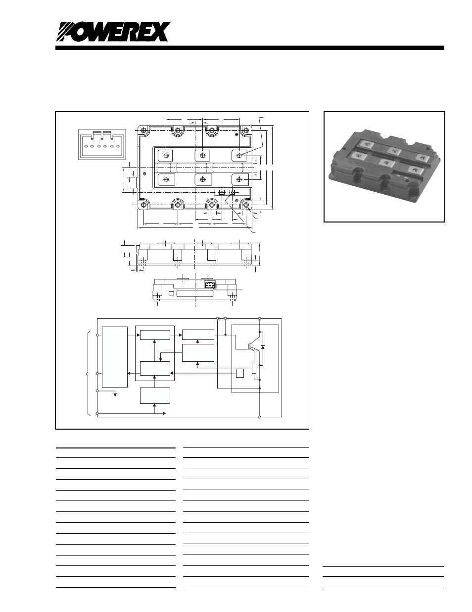
High Voltage Intelligent
Power Module
1200 Amperes/3300 Volts
PM1200HCE330-1
Powerex, Inc., 200 E. Hillis Street, Youngwood, Pennsylvania 15697-1800 (724) 925-7272
1
Dimensions
Inches
Millimeters
A
7.48
±
0.012
190.0
±
0.3
B
5.51
±
0.012
140.0
±
0.3
C
4.88
±
0.012
124.0
±
0.3
D
2.24
±
0.012
57.0
±
0.3
E
1.57
40.0
F
0.51
13.0
G
2.42
±
0.012
61.5
±
0.3
H
0.65
16.5
J
0.55
14.0
K
1.77
45.0
L
0.67
17.0
M
0.59
15.0
Description:
Powerex High Voltage Intelligent
Power Module combines gate drive
and protection circuitry in a fully
isolated package. The new HVIPM
reduces the saturation voltage by
7.5% while maintaining high short
circuit withstanding capability. Gate
drive noise is resolved through the
use of the HVIPM by optimizing the
control of the chip through close
proximity of the gate drive control
circuit.
Features:
□
Control Circuit and Protection
Circuitry for Overcurrent,
Short Circuit and Over-
temperature
□
Low V
CE(sat)
7.5%
Reduction Versus HVIGBT
□
Exterior Package Matches
Standard HVIGBT
□
Optimized Isolation Design to
Satisfy 6KV AC.
Applications:
□
High Power Converters
and Inverters
□
Medium Voltage Drives
□
Traction Drives
Ordering Information:
Example: Select the complete
module number you desire from
the table - i.e. PM1200HCE330-1
is a 1200V (V
CES
), 3300 Ampere
High Voltage Power Module.
Type
Current Rating (A)
V
CES
(V)
PM
3300
1200
Dimensions
Inches
Millimeters
N
1.61
41.0
P
0.62
15.85
R
0.72
18.3
S
0.59
15.0
T
0.26
6.5
U
M8
M8
V
M3
M3
W
1.50 +0.4/-0.0
38.0 +1.0/-0.0
X
0.37
9.3
Y
0.10
2.6
Z
0.91
23.0
AA
0.43
11.0
C
LABEL
X
W
Y
AA
A
D
D
D
L
K
J
H
T (8 PLACES)
V (2 PLACES)
M
B
C
E
S
U
(8 PLACES)
G
F
N
6
TERMINAL ARRANGEMENT
CONTROL CONNECTOR
5
4 3
2 1
V1
VC
ST
CI
NC
FO
P
C
E
C
E
C
G
E
E
R
G
Z
CONTROL
CONNECTOR
FEMALE
(TYPE
IL-AG5-6S-S3C1)
E
G
E
IGBT
FWDI
MAIN
CIRCUIT
GATE DRIVE
OC/SC
OT
CI
FO
VC
UV
VI
CONNECTOR
TO CONTROL CIRCUIT
CONTROL
LOGIC
ASIC
PROTECTION
LOGIC
POWER
FAILURE
DETECTOR
CONTROL
CIRCUIT
GROUND
INPUT
INTERFACE
R.T.C.
(REAL TIME
CONTROL)
CURRENT
SENSOR
THERMAL
SENSOR
Outline Drawing and Circuit Diagram