Vishay semiconductors – C&H Technology VSKE91.. Series User Manual
Page 6
Document Number: 94627
For technical questions, contact:
www.vishay.com
Revision: 09-Mar-11
5
This datasheet is subject to change without notice.
THE PRODUCT DESCRIBED HEREIN AND THIS DATASHEET ARE SUBJECT TO SPECIFIC DISCLAIMERS, SET FORTH AT
www.vishay.com/doc?91000
VSKD91.., VSKC91.., VSKJ91.., VSKE91.. Series
ADD-A-PAK Generation VII
Power Modules Standard Diodes, 100 A
Vishay Semiconductors
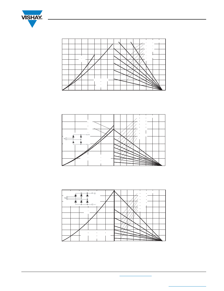
Fig. 7 - Forward Power Loss Characteristics
Fig. 8 - Forward Power Loss Characteristics
Fig. 9 - Forward Power Loss Characteristics
Total RMS output current (A)
Maximum total forward power loss (W)
Maximum allowable ambient temperature (°C)
0
20
40
60
80 100 120 140 160
0
0
0
0
0
0
0
0
0
RthSA = 0.1 °C/W
0.3 °C/W
0.5 °C/W
0.7 °C/W
1 °C/W
1.5 °C/W
3 °C/W
0
20
40
60
80 100 120 140 160
0
20
40
60
80
100
120
140
160
180
200
180°
(Sine)
VSK.91 Series
Per leg
Tj = 150°C
DC
Total output current (A)
Maximum total power loss (W)
0
20
40
60
80 100 120 140 160
RthSA = 0.2 °C/W
0.3 °C/W
0.4 °C/W
0.5 °C/W
0.7 °C/W
1 °C/W
1.5 °C/W
3 °C/W
Maximum allowable ambient temperature (°C)
0
50
100
150
200
0
100
200
300
400
500
600
700
180°
(sine)
180°
(rect)
2 x VSK.91 Series
single phase bridge connected
Tj = 150°C
Total output current (A)
Maximum allowable ambient temperature (°C)
Maximum total power loss (W)
0
20
40
60
80 100 120 140 160
RthSA = 0.1 °C/W
0.2 °C/W
0.3 °C/W
0.5 °C/W
0.7 °C/W
1 °C/W
3 °C/W
0
50
100
150
200
250
300
0
100
200
300
400
500
600
700
800
900
120°
(rect)
3 x VSK.91 Series
three phase bridge connected
Tj = 150°C