Vsk.f200..p series, Vishay high power products, Power modules), 200 a – C&H Technology VSK.F200..P Series User Manual
Page 5: Conduction
www.vishay.com
For technical questions, contact: [email protected]
Document Number: 94422
4
Revision: 03-Jun-08
VSK.F200..P Series
Vishay High Power Products
Fast Thyristor/Diode and Thyristor/Thyristor
(MAGN-A-PAK
TM
Power Modules), 200 A
Note
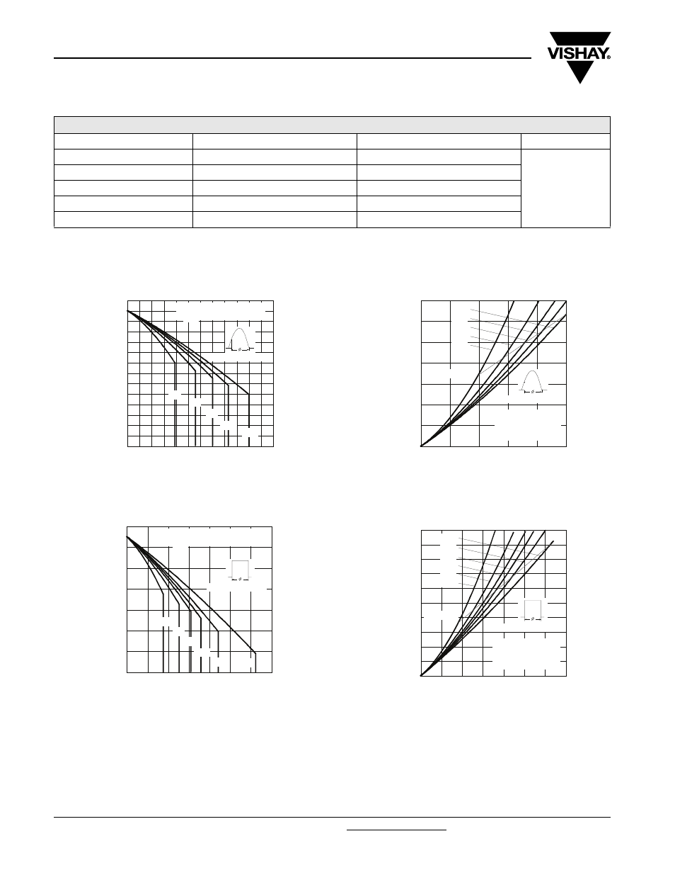
• Table shows the increment of thermal resistance R
thJC
when devices operate at different conduction angles than DC
Fig. 1 - Current Ratings Characteristics
Fig. 2 - Current Ratings Characteristics
Fig. 3 - On-State Power Loss Characteristics
Fig. 4 - On-State Power Loss Characteristics
ΔR
thJC
CONDUCTION
CONDUCTIONS ANGLE
SINUSOIDAL CONDUCTION RECTANGULAR
CONDUCTION UNITS
180°
0.009
0.006
K/W
120°
0.10
0.011
90°
0.014
0.015
60°
0.020
0.020
30°
0.32
0.033
60
70
80
90
100
110
120
130
0
40
80
120
160
200
240
30°
60°
90°
120°
180°
Average On-state Current (A)
Ma
x
imu
m
A
llo
w
a
b
le
Ca
se
T
e
mp
e
ra
tu
re
(°
C)
Cond uc tion Ang le
VSK.F200.. Series
R (DC) = 0.125 K/ W
thJC
60
70
80
90
100
110
120
130
0
50
100
150
200
250
300
350
DC
30°
60°
90°
120°
180°
Average On-state Current (A)
M
a
xi
mu
m
A
llo
wab
le
C
a
se
T
e
mp
er
a
tu
re (
°C
)
Conduction Period
VSK.F200.. Series
R (DC) = 0.125 K/ W
thJC
0
50
100
150
200
250
300
350
0
40
80
120
160
200
RMS Limit
Conduc tion Angle
M
a
x
im
u
m A
v
e
rag
e O
n
-s
ta
te
P
o
we
r L
o
ss
(
W
)
Average On-state Current (A)
180°
120°
90°
60°
30°
VSK.F200.. Series
Per Junc tion
T = 125°C
J
0
50
100
150
200
250
300
350
400
450
500
0
50
100
150
200
250
300
350
DC
180°
120°
90°
60°
30°
RMS Limit
Cond uc tion Period
Ma
x
im
u
m A
v
e
ra
g
e
O
n
-s
ta
te
P
o
w
e
r L
o
ss
(
W
)
Average On-state Current (A)
VSK.F200.. Series
Per Junc tion
T = 125°C
J