Protection function timing diagrams – C&H Technology PS21997-4A User Manual
Page 7
PS21997-4, PS21997-4A
Intellimod™ Module
Dual In-line Intelligent Power Module
30 Amperes/600 Volts
Powerex, Inc., 173 Pavilion Lane, Youngwood, Pennsylvania 15697-1800 (724) 925-7272
6
10/09
Protection Function Timing Diagrams
a1
SC
SC REFERENCE VOLTAGE
RC CIRCUIT TIME CONSTANT DELAY
a2
a3
a4
a8
a5
a7
a6
SET
RESET
N-SIDE
CONTROL INPUT
PROTECTION
CIRCUIT STATE
INTERNAL IGBT GATE
SENSE VOLTAGE OF RS
OUTPUT CURRENT IC
FAULT OUTPUT FO
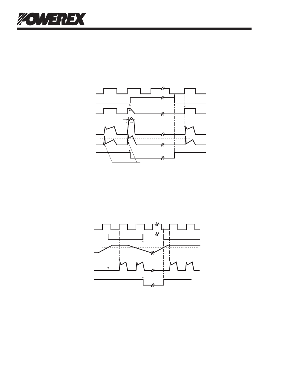
Short Circuit Protection (N-side Only with External Shunt Resistor and RC Filter)
a1: Normal operation – IGBT turns on and carries current.
a2: Short circuit current is detected (SC trigger).
a3: All N-side IGBT's gate are hard interrupted.
a4: All N-side IGBT's turn off.
a5: FO output wirh a fixed pulse width (determined by the external capacitance CFO).
a6: Input "L" – IGBT off.
a7: Input "H" – IGBT on, but during the FO output perid the IGBT will not turn on.
a8: IGBT turns on when L→H signal is input after FO is reset.
b1
b4
b5
b2
UVDt
b7
b3
SET
RESET
RESET
UVDr
b6
CONTROL INPUT
PROTECTION
CIRCUIT STATE
CONTROL SUPPLY
VOLTAGE VD
OUTPUT CURRENT IC
FAULT OUTPUT FO
Under-Voltage Protection (N-side , UVD)
b1: Control supply voltage VD rises – After VD level reaches under voltage reset level (UVDr), the circuits
start to operate when next input is applied.
b2 : Normal operation – IGBT turns on and carries current.
b3: VD level dips to under voltage trip level (UVDt).
b4: All N-side IGBT’s turn off in spite of control input condition.
b5: FO is low for a minimum period determined by the capacitance CFO but continuously during UV period.
b6: VD level reaches UVDr.
b7: Normal operation – IGBT turns on and carries current.