Vishay semiconductors – C&H Technology VSKN26.. Series User Manual
Page 6
Document Number: 94629
For technical questions within your region, please contact one of the following:
www.vishay.com
Revision: 17-May-10
,
,
5
VSKT26.., VSKH26.., VSKL26.., VSKN26.. Series
ADD-A-PAK Generation VII Power Modules
Thyristor/Diode and Thyristor/Thyristor, 27 A
Vishay Semiconductors
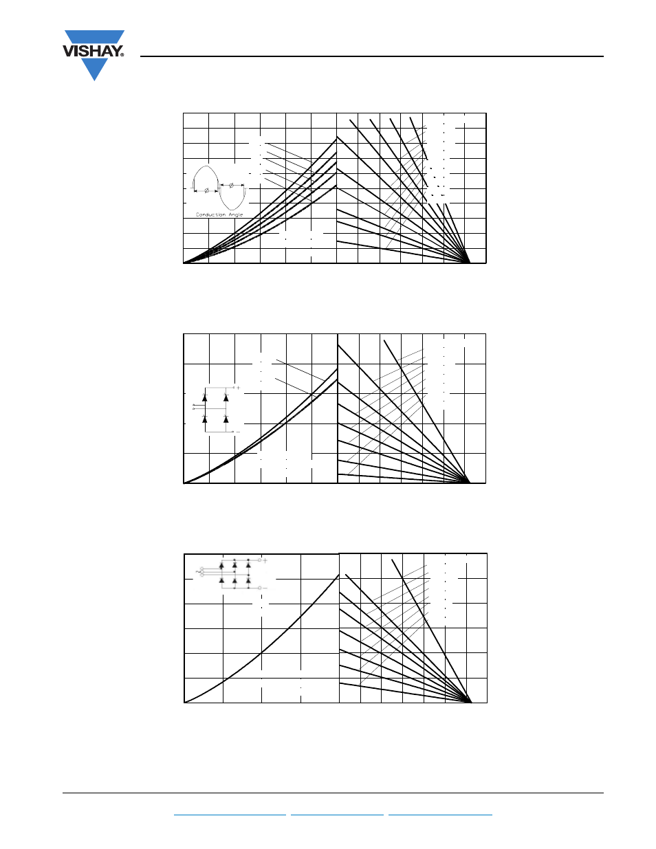
Fig. 7 - On-State Power Loss Characteristics
Fig. 8 - On-State Power Loss Characteristics
Fig. 9 - On-State Power Loss Characteristics
Total RMS output current (A)
Maximum total on-state power loss (W)
Maximum allowable ambient temperature (°C)
0
20
40
60
80
100 120 140
RthSA = 0.1 °C/W
0.3 °C/W
0.5 °C/W
0.7 °C/W
1 °C/W
1.5 °C/W
2 °C/W
3 °C/W
4 °C/W
8 °C/W
0
10
20
30
40
50
60
0
10
20
30
40
50
60
70
80
90
100
180°
120°
90°
60°
30°
VSK.26 Series
Per module
Tj = 125°C
Total output current (A)
Maximum total power loss (W)
Maximum allowable ambient temperature (°C)
0
20
40
60
80
100 120 140
RthSA = 0.1 °C/W
0.3 °C/W
0.5 °C/W
0.7 °C/W
1 °C/W
1.5 °C/W
3 °C/W
8 °C/W
0
10
20
30
40
50
60
0
50
100
150
200
250
180°
(sine)
180°
(rect)
2 x VSK.26 Series
single phase bridge connected
Tj = 125°C
∼
Total output current (A)
Maximum allowable ambient temperature (°C)
Maximum total power loss (W)
0
20
40
60
80
100 120 140
RthSA = 0.1 °C/W
0.3 °C/W
0.4 °C/W
0.5 °C/W
0.7 °C/W
1 °C/W
1.5 °C/W
3 °C/W
0
20
40
60
80
0
50
100
150
200
250
300
120°
(rect)
3 x VSK.26 Series
three phase bridge connected
Tj = 125°C