Vishay semiconductors – C&H Technology VSKN26.. Series User Manual
Page 5
www.vishay.com
For technical questions within your region, please contact one of the following:
Document Number: 94629
4
,
,
Revision: 17-May-10
VSKT26.., VSKH26.., VSKL26.., VSKN26.. Series
Vishay Semiconductors
ADD-A-PAK Generation VII Power Modules
Thyristor/Diode and Thyristor/Thyristor, 27 A
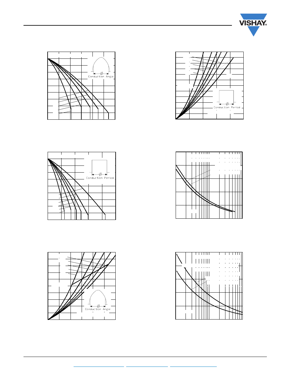
Fig. 1 - Current Ratings Characteristics
Fig. 2 - Current Ratings Characteristics
Fig. 3 - On-State Power Loss Characteristics
Fig. 4 - On-State Power Loss Characteristics
Fig. 5 - Maximum Non-Repetitive Surge Current
Fig. 6 - Maximum Non-Repetitive Surge Current
Average on-state current (A)
Maximum allowable case temperature (°C)
0
5
10
15
20
25
30
80
90
100
110
120
130
180°
120°
90°
60°
30°
RthJC (DC) = 0.76°C/W
0
10
20
30
40
50
80
90
100
110
120
130
180°
120°
90°
60°
30°
DC
RthJC (DC) = 0.76 °C/W
Average on-state current (A)
Maximum allowable case temperature (°C)
Average on-state current (A)
Maximum average on-state power loss (W)
0
5
10
15
20
25
30
0
10
20
30
40
50
180°
120°
90°
60°
30°
RMS limit
Per leg, Tj = 125°C
Average on-state current (A)
Maximum average on-state power loss (W)
0
10
20
30
40
50
0
10
20
30
40
50
60
180°
120°
90°
60°
30°
RMS limit
DC
Per leg, Tj = 125°C
Peak half sine wave on-state current (A)
Number of equal amplitude half cycle current pulses (N)
1
10
100
150
200
250
300
350
400
At any rated load condition and with
rated Vrrm applied following surge
Initial Tj = Tj max
@ 60 Hz 0.0083 s
@ 50 Hz 0.0100s
Per leg
Peak half sine wave on-state current (A)
Pulse train duration (s)
0.01
0.1
1
150
200
250
300
350
400
Maximum Non-repetitive Surge
Current. Control
of conduction may not be maintained.
Versus Pulse Train Duration
Initial Tj = 125°C
No Voltage Reapplied
Rated Vrrm reapplied
Per leg