Vishay semiconductors – C&H Technology T85HFL Series User Manual
Page 4
Document Number: 93184
For technical questions within your region, please contact one of the following:
www.vishay.com
Revision: 19-May-10
,
,
3
T40HFL, T70HFL, T85HFL Series
Fast Recovery Diodes
(T-Modules), 40 A/70 A/85 A
Vishay Semiconductors
Note
(1)
Tested on LEM 300 A diodemeter tester
Note
(1)
A mounting compound is recommended and the torque should be rechecked after a period of about 3 hours to allow for the spread of
the compound
Note
• The table above shows the increment of thermal resistance R
thJC
when devices operate at different conduction angles than DC
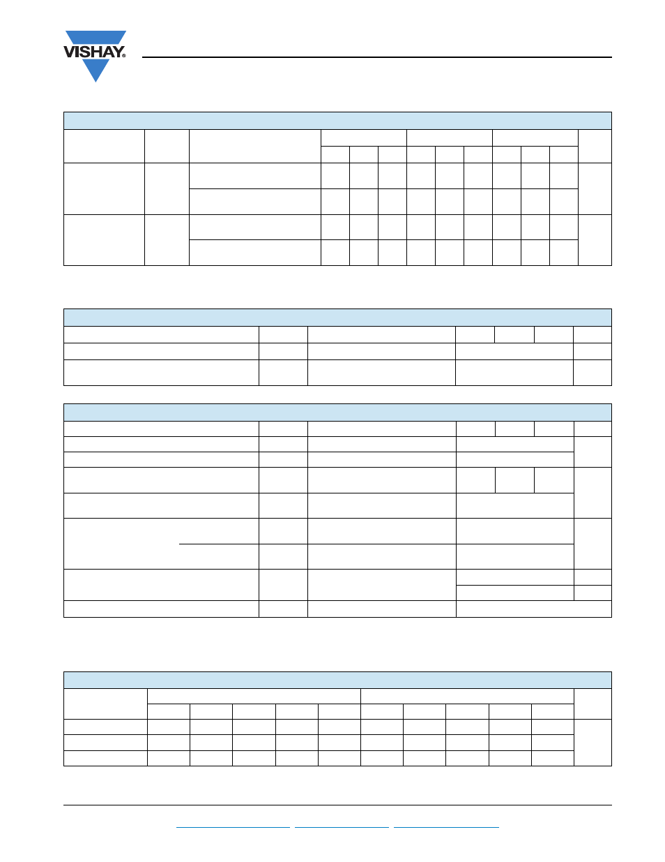
REVERSE RECOVERY CHARACTERISTICS
PARAMETER
SYMBOL
TEST CONDITIONS
(1)
T40HFL
T70HFL
T85HFL
UNITS
S02
S05
S10
S02
S05
S10
S02
S05
S10
Maximum reverse
recovery time
t
rr
T
J
= 25 °C, -dI
F
/dt = 100 A/μs
I
F
= 1 A to V
R
= 30 V
70
110
270
70
110
270
80
120
290
ns
T
J
= 25 °C, -dI
F
/dt = 25 A/μs
I
FM
=
π x rated I
F(AV)
, V
R
= - 30 V
200
500
1000
200
500
1000
200
500
1000
Maximum reverse
recovery charge
Q
rr
T
J
= 25 °C, -dI
F
/dt = 100 A/μs
I
F
= 1 A to V
R
= 30 V
0.25
0.4
1.35
0.25
0.4
1.35
0.3
0.6
1.6
μC
T
J
= 25 °C, -dI
F
/dt = 25 A/μs
I
FM
=
π x rated I
F(AV)
, V
R
= - 30 V
0.55
2.0
8.0
0.6
2.1
8.5
0.8
3.5
1.5
BLOCKING
PARAMETER
SYMBOL
TEST CONDITIONS
T40HFL T70HFL T85HFL
UNITS
Maximum peak reverse leakage current
I
RRM
T
J
= 125 °C
20
mA
RMS isolation voltage
V
ISOL
50 Hz, circuit to base, all terminals
shorted, T
J
= 25 °C, t = 1 s
3500
V
THERMAL AND MECHANICAL SPECIFICATIONS
PARAMETER
SYMBOL
TEST CONDITIONS
T40HFL T70HFL T85HFL
UNITS
Junction operating temperature range
T
J
- 40 to 125
°C
Storage temperature range
T
Stg
- 40 to 150
Maximum internal thermal resistance,
junction to case per module
R
thJC
DC operation
0.85
0.53
0.46
K/W
Thermal resistance,
case to heatsink per module
R
thCS
Mounting surface, flat, smooth
and greased
0.2
Mounting torque ± 10 %
base to heatsink
M3.5 mounting screws
(1)
Non-lubricated threads
1.3 ± 10 %
Nm
busbar to terminal
M5 screws terminals
Non-lubricated threads
3 ± 10 %
Approximate weight
See dimensions -
link at the end of datasheet
54
g
19
oz.
Case style
D-55 (T-module)
ΔR CONDUCTION
DEVICES
SINUSOIDAL CONDUCTION AT T
J
MAXIMUM
RECTANGULAR CONDUCTION AT T
J
MAXIMUM
UNITS
180°
120°
90°
60°
30°
180°
120°
90°
60°
30°
T40HFL
0.06
0.08
0.10
0.14
0.24
0.05
0.08
0.10
0.15
0.24
K/W
T70HFL
0.05
0.06
0.08
0.11
0.19
0.04
0.06
0.08
0.12
0.19
T85HFL
0.04
0.05
0.06
0.09
0.15
0.03
0.05
0.07
0.09
0.015