Vishay semiconductors, Thermal and mechanical specifications – C&H Technology VS-GA400TD60S User Manual
Page 4
Document Number: 93363
For technical questions, contact:
www.vishay.com
Revision: 31-May-11
3
This document is subject to change without notice.
THE PRODUCTS DESCRIBED HEREIN AND THIS DOCUMENT ARE SUBJECT TO SPECIFIC DISCLAIMERS, SET FORTH AT
www.vishay.com/doc?91000
GA400TD60S
Dual INT-A-PAK Low Profile "Half-Bridge"
(Standard Speed IGBT), 400 A
Vishay Semiconductors
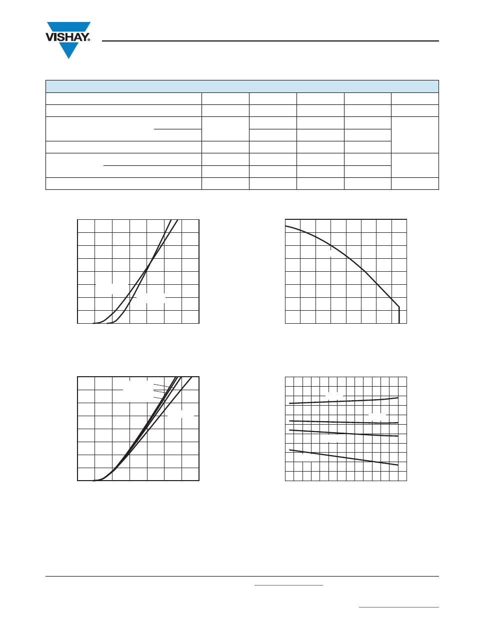
Fig. 1 - Typical Output Characteristics,
T
J
= 25 °C, V
GE
= 15 V
Fig. 2 - Typical Output Characteristics,
T
J
= 125 °C
Fig. 3 - Maximum DC IGBT Collector Current vs.
Case Temperature
Fig. 4 - Typical IGBT Collector to Emitter Voltage vs.
Junction Temperature,
V
GE
= 15 V
THERMAL AND MECHANICAL SPECIFICATIONS
PARAMETER
SYMBOL
MIN. TYP. MAX.
UNITS
Operating junction and storage temperature range
T
J
, T
Stg
- 40
-
150
°C
Junction to case per leg
IGBT
R
thJC
-
-
0.08
°C/W
Diode
-
-
0.4
Case to sink per module
R
thCS
-
0.05
-
Mounting torque
case to heatsink: M6 screw
4
-
6
Nm
case to terminal 1, 2, 3: M5 screw
2
-
4
Weight
-
270
-
g
I
C
(A)
V
CE
(V)
0.25
0.50
1.00
1.50
2.00
0.75
1.25
1.75
0
93363_01
800
200
100
400
300
600
500
700
T
J
= 25 °C
T
J
= 125 °C
I
C
(A)
V
CE
(V)
0.25
0.50
1.00
1.50
2.00
1.25
0.75
1.75
93363_02
0
800
200
100
400
300
600
500
700
V
GE
= 9 V
V
GE
= 12 V
V
GE
= 15 V
V
GE
= 18 V
Allowable Case Temperature (°C)
I
C
- Continuous Collector Current (A)
300
100
800
500
400
200
600
700
0
100
160
0
40
60
140
80
120
20
93363_03
DC
V
CE
(V)
T
J
(°C)
20
40
80
120
160
60
100
140
0.6
1.0
1.4
93363_04
1.7
0.9
1.3
0.8
1.2
1.6
0.7
1.1
1.5
400 A
600 A
300 A
100 A