Vishay semiconductors, Diodes, 5 a – C&H Technology GB05XP120KTPbF User Manual
Page 8
Document Number: 93912
For technical questions within your region, please contact one of the following:
www.vishay.com
Revision: 03-Aug-10
,
,
7
GB05XP120KTPbF
Three Phase Inverter Module in MTP Package
1200 V NPT IGBT and HEXFRED
®
Diodes, 5 A
Vishay Semiconductors
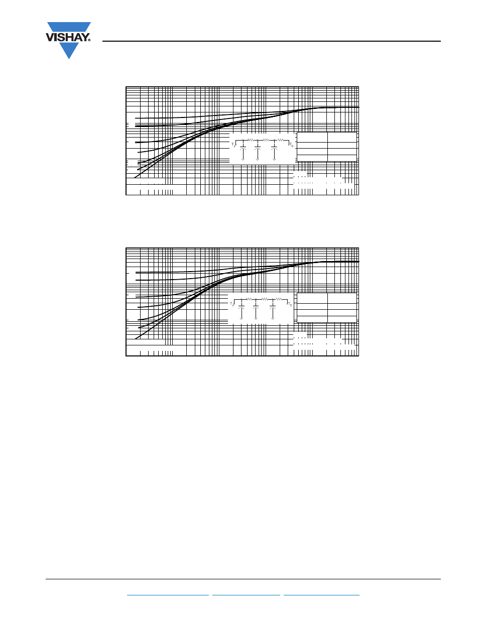
Fig. 20 - Maximum Transient Thermal Impedance, Junction to Case (IGBT)
Fig. 21 - Maximum Transient Thermal Impedance, Junction to Case (Diode)
1E-05
1E-04
1E-03
1E-02
1E-01
1E+00
0.01
0.1
1
10
SINGLE PULSE
(THERMAL RESPONSE)
0.5
0.3
0.1
0.05
0.02
0.01
Ri (°C/W)
0.660
0.536
1.483
τi (sec)
0.00037
0.001664
0.037405
Notes:
1. Duty Factor D = t1/t2
2. Peak Tj = P dm x Zthjc + tc
t1 , Rectangular Pulse Duration (sec)
T
h
er
mal
Resp
on
se (Z
th
JC
)
τ
J
τ
1
τ
1
τ
2
τ
2
τ
3
τ
3
R
1
R
1
R
2
R
2
R
3
R
3
Ci
i
/Ri
Ci=
τi/Ri
1E-05
1E-04
1E-03
1E-02
1E-01
1E+00
0.01
0.1
1
10
SINGLE PULSE
(THERMAL RESPONSE)
0.5
0.3
0.1
0.05
0.02
0.01
Ri (°C/W)
1.684
1.683
0.833
τi (sec)
0.001077
0.020815
0.040397
Notes:
1. Duty Factor D = t1/t2
2. Peak Tj = P dm x Zthjc + tc
t1 , Rectangular Pulse Duration (sec)
T
h
er
mal
Respon
se (Zth
JC
)
τ
J
τ
1
τ
1
τ
2
τ
2
τ
3
τ
3
R
1
R
1
R
2
R
2
R
3
R
3
Ci
i
/Ri
Ci=
τi/Ri