Vishay semiconductors, Diodes, 5 a – C&H Technology GB05XP120KTPbF User Manual
Page 4
Document Number: 93912
For technical questions within your region, please contact one of the following:
www.vishay.com
Revision: 03-Aug-10
,
,
3
GB05XP120KTPbF
Three Phase Inverter Module in MTP Package
1200 V NPT IGBT and HEXFRED
®
Diodes, 5 A
Vishay Semiconductors
Notes
(1)
T
0
, T
1
are thermistor´s temperatures
(2)
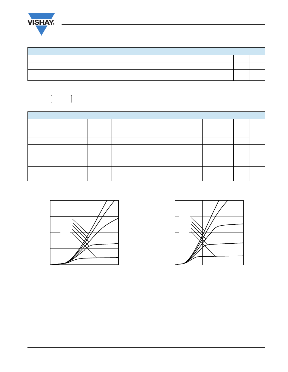
Fig. 1 - Typical Output Characteristics
T
J
= 25 °C
Fig. 2 - Typical Output Characteristics
T
J
= 125 °C
THERMISTOR SPECIFICATIONS (T CODE ONLY)
PARAMETER
SYMBOL
TEST CONDITIONS
MIN.
TYP.
MAX.
UNITS
Resistance
R
0
(1)
T
0
= 25 °C
-
30
-
k
Sensitivity index of the
thermistor material
(1)(2)
T
0
= 25 °C
T
1
= 85 °C
-
4000
-
K
R
0
R
1
-------
1
T
0
------
1
T
1
------
–
exp
=
THERMAL AND MECHANICAL SPECIFICATIONS
PARAMETER
SYMBOL
TEST CONDITIONS
MIN.
TYP.
MAX.
UNITS
Operating junction
temperature range
T
J
- 40
-
150
°C
Storage temperature range
T
Stg
- 40
-
125
Junction to case
IGBT
R
thJC
-
-
2.68
°C/W
Diode
-
-
4.2
Case to sink per module
R
thCS
Heatsink compound thermal conductivity = 1 W/mK
-
0.06
-
Mounting torque
-
-
4
Nm
Weight
-
65
-
g
0
2
4
6
0
5
10
15
20
Vge=18V
Vge=15V
Vge=12V
Vge=10V
Vge=8V
Ic
e
(
A
)
Vce (V)
0
2
4
6
8
10
0
5
10
15
20
Vge=18V
Vge=15V
Vge=12V
Vge=10V
Vge=8V
Vce (V)
Ic
e
(
A
)