3 adjustment system – VEGA VEGAPULS SR 68 Modbus and Levelmaster protocol User Manual
Page 36
36
6 Set up the sensor with the display and adjustment module
VEGAPULS SR 68 • Modbus and Levelmaster protocol
41371-EN-130624
Note:
If you intend to retrofit the instrument with a display and adjustment
module for continuous measured value indication, a higher cover with
an inspection glass is required.
6.3 Adjustment system
1
2
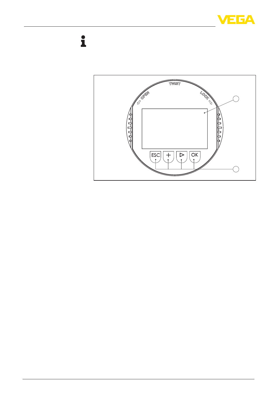
Fig. 34: Display and adjustment elements
1 LC display
2 Adjustment keys
•
[OK] key:
– Move to the menu overview
– Confirm selected menu
– Edit parameter
– Save value
•
[->] key:
– Presentation, change measured value
– Select list entry
– Select editing position
•
[+] key:
– Change value of the parameter
•
[ESC] key:
– Interrupt input
– Jump to next higher menu
The sensor is adjusted via the four keys of the display and adjust-
ment module. The LC display indicates the individual menu items. The
functions of the individual keys are shown in the above illustration.
Approx. 60 minutes after the last pressing of a key, an automatic reset
to measured value indication is triggered. Any values not confirmed
with [OK] will not be saved.
Key functions
Adjustment system