VEGA VEGASWING 66 - two-wire With SIL qualification User Manual
Page 26
26
6 Setup
VEGASWING 66 • - two-wire
44952-EN-130805
Check if the switching status changes (signal lamp - switching
status). By doing so, you can check the function of the measuring
system.
If this is not the case, then there is a fault in the measuring sys-
tem.
Make sure the connected downstream devices are activated dur-
ing the function test.
You can find the coverage of the test in the Safety Manual.
Implementation - Function test
If you are using a signal conditioning instrument of type VEGATOR for
this purpose, you can also carry out the test with the integrated test
key. The test key is recessed in the front plate of the signal condi-
tioning insturment. Push the test key for > 2 seconds with a suitable
object (screwdriver, pen, etc.).
When the VEGASWING 66 is connected to a processing system or
an SPLC, you have to interrupt the connection cable to the sensor for
> 2 seconds. The switching delay must be set to 0.5 s.
After releasing the test key or interrupting the connection cable to the
sensor, the complete measuring system can be checked on correct
function. The following operating conditions are simulated during the
test:
•
Fault message
•
Empty signal
•
Full signal
2
1
3
4
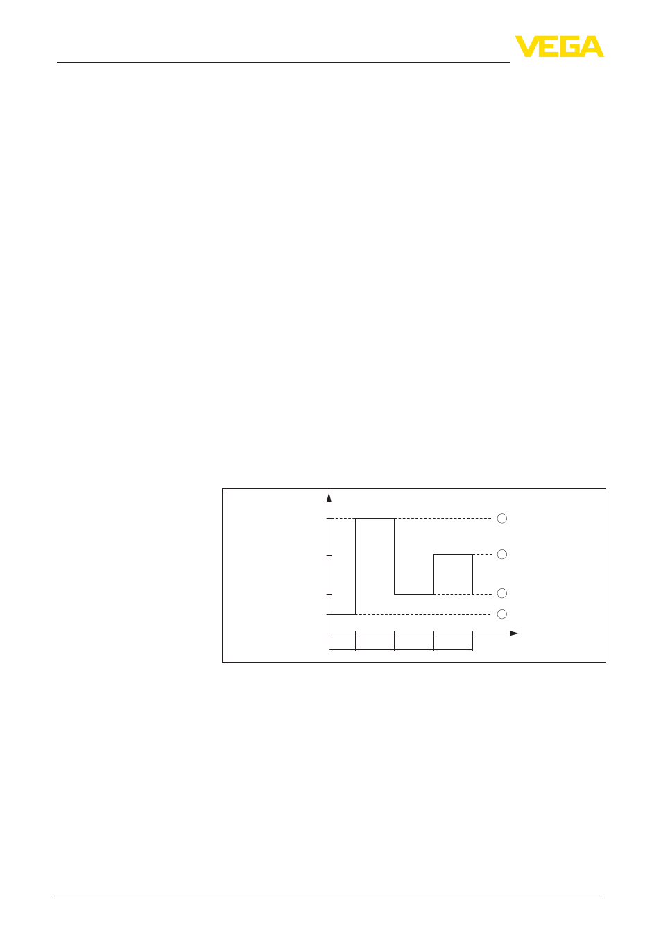
16
I/mA
8
3,6
1,0
1,5
1,5
1,5
t/s
23,5
Fig. 37: Flow chart of the function test
1 Fault message
2 Full signal
3 Empty signal
4 Start-up phase
Check if all three switching conditions occur in the correct sequence
and the stated time period. If this is not the case, there is a fault in the
measuring system (see also the operating instructions manual of the
signal conditioning instrument). Keep in mind that connected instru-
ments are activated during the function test. By doing this, you can
check the correct function of the measuring system.