3 wiring plan, single chamber housing – VEGA VEGAFLEX 67 (-200…+400°C) 4 … 20 mA_HART two-wire User Manual
Page 18
2
I
f an indicating and adjustment module is installed, remove it by
turning it to the left.
3
L
oosen compression nut of the cable entry
4
R
emove approx. 10 cm (4 in) of the cable mantle, strip approx.
1
cm (0.4 in) of insulation from the ends of the individual wires
5
I
nsert the cable into the sensor through the cable entry
6
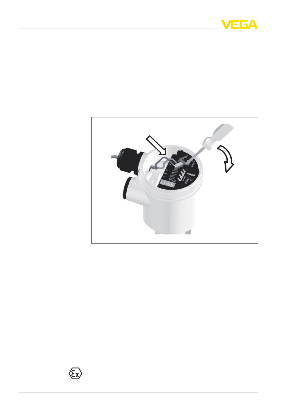
L
ift the opening levers of the terminals with a screwdriver (see
following illustration)
7
I
nsert the wire ends into the open terminals according to the wiring
plan
Fig. 7: Connection steps 6 and 7
8
P
ress down the opening levers of the terminals, you will hear the
terminal spring closing
9
C
heck the hold of the wires in the terminals by lightly pulling on
them
10 C
onnect the screen to the internal ground terminal, connect the
outer ground terminal to potential equalisation
11 T
ighten the compression nut of the cable entry. The seal ring must
completely encircle the cable
12 S
crew the housing cover back on
T
he electrical connection is finished.
5
.3 Wiring plan, single chamber housing
T
he following illustrations apply to the non-Ex as well as to the Ex-ia
version.
18
VEGAFLEX
67 • 4 … 20
mA/HART - two-wire
5 C
onnecting to power supply
32311
-EN
-120329