Technical information, Electrical connection, Mounting instructions – VEGA VEGAMET 407 Z User Manual
Page 8
8
Technical Information
VEGAMET 407 Z
18
17
16
15
14
13
N
L1
9
2
1
+
–
–
+
–
+
5
7
+
1
Sensor 1
1
2
3
4 … 20 mA
8
6
18
17
16
15
13
9
2
5
7
1
8
6
14
Sensor 1
1
2
3
0 … 20 mA
-
+
Electrical connection
Installation regulations:
- The wiring between VEGAMET 407 Z and sensor
(capacitive measuring electrode or pressure
transmitter) can be made with standard cable.
- In case of strong electromagnetic interferences,
screened cable must be used.
The screening must be earthed at one sensor
end.
Signal conditioning instrument
back view (type plate)
Plug-in socket with
terminals
VEGAMET 407 Z
Selection of the
current output
Alarm signals
Fault-monitoring relay
Supply voltage
(see data plate)
Voltage otuput 0 … 10 V
Voltage otuput 0 … 5 V
Current output 0/4 … 20 mA
capacitive
measuring
electrode
pressure
transmitter
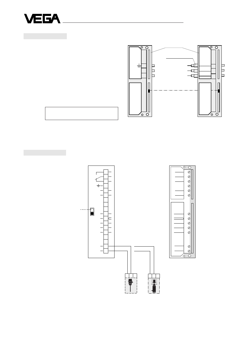
Mounting instructions
14
13
VEGAMET
VEGAMET
15
14
13
15
N
L1
The plug-in base is provided with
- field terminals
- interconnection pins
- spacers for installation in series
- key coded
For installation in series the interconnection
pins are the power supply connections and
the distance sleeves ensure that adjacent
instruments have a minimum gap of 5 mm
between each other.
Remove the interconnection pins on the first
plug-in socket.
Warning:
Beware of high voltage on
power supply terminals.
Plug-in base
Spacers
Key code
Interconnecting
pins for supply
voltage
In case of single mounting remove the interconnec-
tion pins and spacers, connect the supply voltage
directly.
The key coded base prevents other series 400
instruments being inserted.
Use adapter no. 040 002 for mounting on standard
rail.