Figure 5. spring-lock cut away, Periodic maintenance – Veris Verabar V150 Installation Instructions User Manual
Page 4
• Using a torque wrench, tighten the three packing
bolts to the appropriate torque value listed in the
table below.
Sensor Size
Packing Bolt
Torque (in-lbs)
Packing Bolt
Torque (ft-lbs)
–05 50 4.2
–10 100 8.3
–15 170 14.1
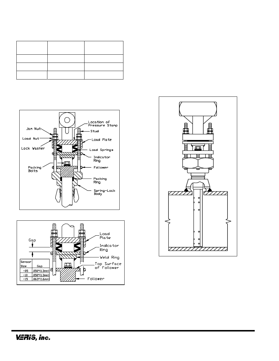
Note: The weld on the weld ring (Figure 6) should
not contact the top surface of the follower. If the weld
on the weld ring comes into contact with the follower,
the sensor will not be properly bottomed in the pipe.
If this occurs, consult the factory before proceeding.
Figure 5. Spring-Lock Cut Away
Figure 6. Proper Spring Compression
5.5
Install Instrument Valves or Manifold
5.5.1 Valves
If the Verabar does not have a valve head, install
instrument valves using proper thread sealant. Be sure
instrument shut-off valves are installed and shut prior to
repressurizing the pipe.
5.5.2 Manifold
If the Verabar has a direct or integral manifold, be sure
the high and low-pressure block valves are shut off
prior to repressurizing the pipe.
5.6
Pressurize Pipe and Retighten Bolts
Pressurize the pipe and check for leaks. If leaks are
present, retighten the packing bolts until leaking is
eliminated. Verify that the distance between the load
plate and the indicator ring is approximately 0.050”
(1.3mm) for –05 and –10 sensors and 0.063” (1.6mm)
for –15 sensors; make adjustments as required.
The Verabar is now properly installed (Figure 7).
Figure 7. Installed V150
Periodic Maintenance
The assembly should be periodically checked. Verify
that no leaks are present. Tighten the packing bolts if
necessary.
6315 Monarch Park Place
• Niwot, CO 80503 USA • Phone: (303) 652-8550
IO-150
-V
WI-CS-022 REV B (6/08)
Fax: (303) 652-8552
• Email: [email protected] • Website: www.veris-inc.com
Printed in USA