2weld threadolet to pipe, 4insert sensor – Veris Verabar V150 Installation Instructions User Manual
Page 3
5.2
Weld Threadolet to Pipe
• With the follower and packing rings already in
place, loosely insert the sensor into the Spring-
Lock body (see Figure 2). Thread the Spring-
Lock body into the threadolet (hand tight), then
insert the complete assembly into the pipe. This
will assure proper alignment of the threadolet to
the hole already drilled in the pipe.
• Using the appropriate weld gap (1/16” [1.5mm]
typical), tack weld the threadolet into position,
then remove the sensor and Spring-Lock body.
Protect threads on the threadolet and finish
welding the threadolet to the pipe per applicable
codes (see Figure 3).
Figure 3. Weld Gap
5.3 Thread Packing Body into Threadolet
Using appropriate pipe thread sealant, thread the
Spring-Lock body into the threadolet.
5.4 Insert
Sensor
• With the follower and packing rings already in
place (factory assembled), insert the sensor into
the Spring-Lock body until the tip of the sensor
hits the opposite side of the pipe. Note, the three
studs must pass through the indicator ring and
the load plate.
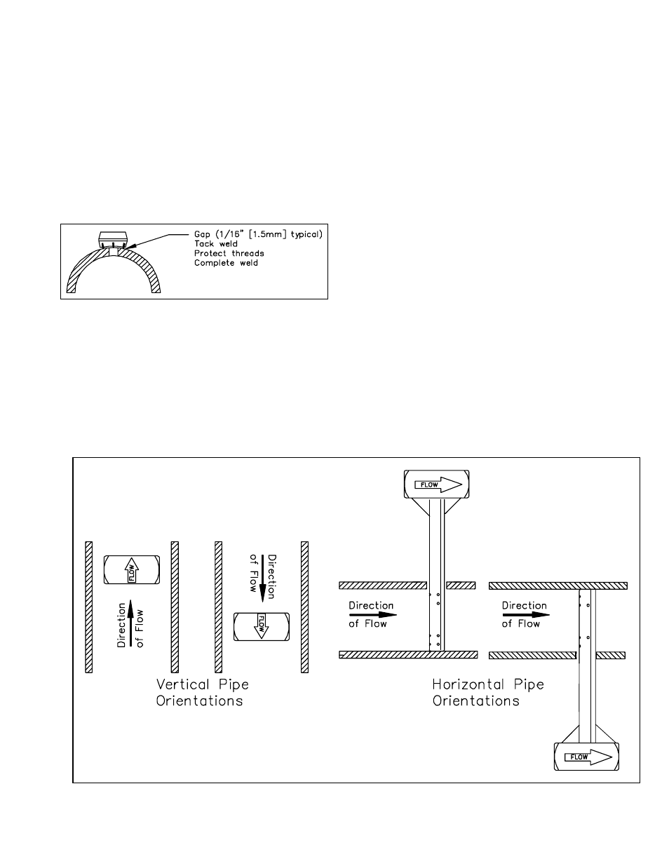
• Align the head of the sensor so that the arrow
labeled “flow” on the head is in the direction of
the flow in the pipe to within 3° (Figure 4).
Maintain the head in this position for the
remainder of the installation.
• Place the three lock washers and the three load
nuts on the studs and tighten. Tighten the load
nuts until the load plate is 0.050” (1.3mm) from
the indicator ring for –05 and –10 sensors. For
–15 sensors, the load plate should be 0.063”
(1.6mm) from the indicator ring (Figure 6). For
–05 sensors, this can be done by tightening all
the load nuts until the load plate just touches the
indicator ring and then backing off all the load
nuts one complete turn. For –10 and –15
sensors, this can be done by tightening all the
load nuts until the load plate just touches the
indicator ring and then backing off all the load
nuts ¾ of a turn. The load springs are now
properly set.
• Thread on the three jam nuts and tighten until
they are resting hand-tight against the lock nuts.
Place a backup wrench on the load nut to
prevent it from rotating. While not allowing the
load nut to rotate, tighten the jam nuts 1/8 turn
beyond hand tight.
Figure 4. Orientation of Flow Arrow