Velleman projects K6714 Assembly instructions User Manual
Page 11
11
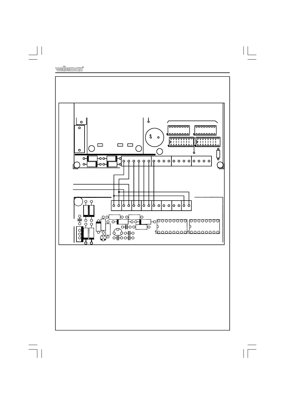
Test and connections
2.
Connect the board to the 10 channel, 2 wire remote control K8023
(see Fig. 2.0) :
FIG 2.0
D5
T1 C3
R
13
Z
D
1
D
4
LD11
D
3
C2
V
R
1
C
4
D
2
SK1
R
11
D
1
R12
12..15Vin
+VTX-
SK6
VELLEMAN P8023R'1
R14
C6
C1
IC2
5
SK2
SK3
R15
D6
1
2
3
4
SK5
SK4
6
7
8
9
IC3
SK7
+Vext
10
GND
IC1
SW1
MANUAL SWITCHING OF CHANNELS
11
J20
D18
D17
F1
J18
D19
D20
GND
VB
1
2
J19
3
4
5
6
7
8
10
9
TRAFO
6
220
125
0
6
0
C17
2
1
4
3
5 6
R
1
7
J21
13
12
14 15
16
SW2
IC2
J
7 8
9 10 11 12
13 14
16
15
SK8
FROM K8023S
VELLEMAN P6714'1
See also other documents in the category Velleman projects Hardware:
- K7000 Assembly instructions (12 pages)
- K8042 Assembly instructions (12 pages)
- EDU10 Assembly instructions (24 pages)
- K2601 Assembly instructions (12 pages)
- K8039 Assembly instructions (20 pages)
- K8090 Assembly instructions (12 pages)
- K4305 Assembly instructions (14 pages)
- K8038 Assembly instructions (16 pages)
- K8018B Assembly instructions (16 pages)
- K8050 Assembly instructions (20 pages)
- K8063 Infosheet (2 pages)
- VM152 Datasheet (1 page)
- K8006 Assembly instructions (16 pages)
- K8059 Infosheet (1 page)
- KA02 Datasheet (1 page)
- K2570 Assembly instructions (8 pages)
- K7102 Assembly instructions (12 pages)
- EDU08 Datasheet (1 page)
- K8092 Infosheet (1 page)
- K2543 Assembly instructions (12 pages)
- VMA03 Datasheet (1 page)
- MK179 Datasheet (1 page)
- K2579 Assembly instructions (12 pages)
- EDU05 (15 pages)
- K4040 Assembly instructions (28 pages)
- K7203 Assembly instructions (12 pages)
- K8027 Assembly instructions (12 pages)
- K8023 Assembly instructions (20 pages)
- MK195 Datasheet (1 page)
- K8008 Assembly instructions (16 pages)
- K5600R Assembly instructions (14 pages)
- VM110N Datasheet (1 page)
- MK180 Datasheet (1 page)
- MK176 Datasheet (1 page)
- K7302 Assembly instructions (12 pages)
- MK190 Datasheet (1 page)
- VM179 Datasheet (1 page)
- K8049 Assembly instructions (12 pages)
- MK153 Assembly instructions (1 page)
- VM8095 Datasheet (1 page)
- VM134 Datasheet (1 page)
- K8077 Infosheet (1 page)
- K5201 Assembly instructions (16 pages)
- K8096 Assembly instructions (16 pages)