12 13.connection and use, Fig 2 fig1 – Velleman projects K5600R Assembly instructions User Manual
Page 12
_______________________________________________________________________________________________________________________________________________________
12
13.CONNECTION AND USE
A- Power supply:
Connect the unit to a DC supply voltage from minimum 12V to maximum 28V.
A standard 12V / 800mA adapter (our type PS1208) can also be used, the inside
of the connector must be connected to the positive terminal.
Standard wires can also be used and soldered at the + and - connection.
12...28VDC/800mA IN
SK1
+
-
SW
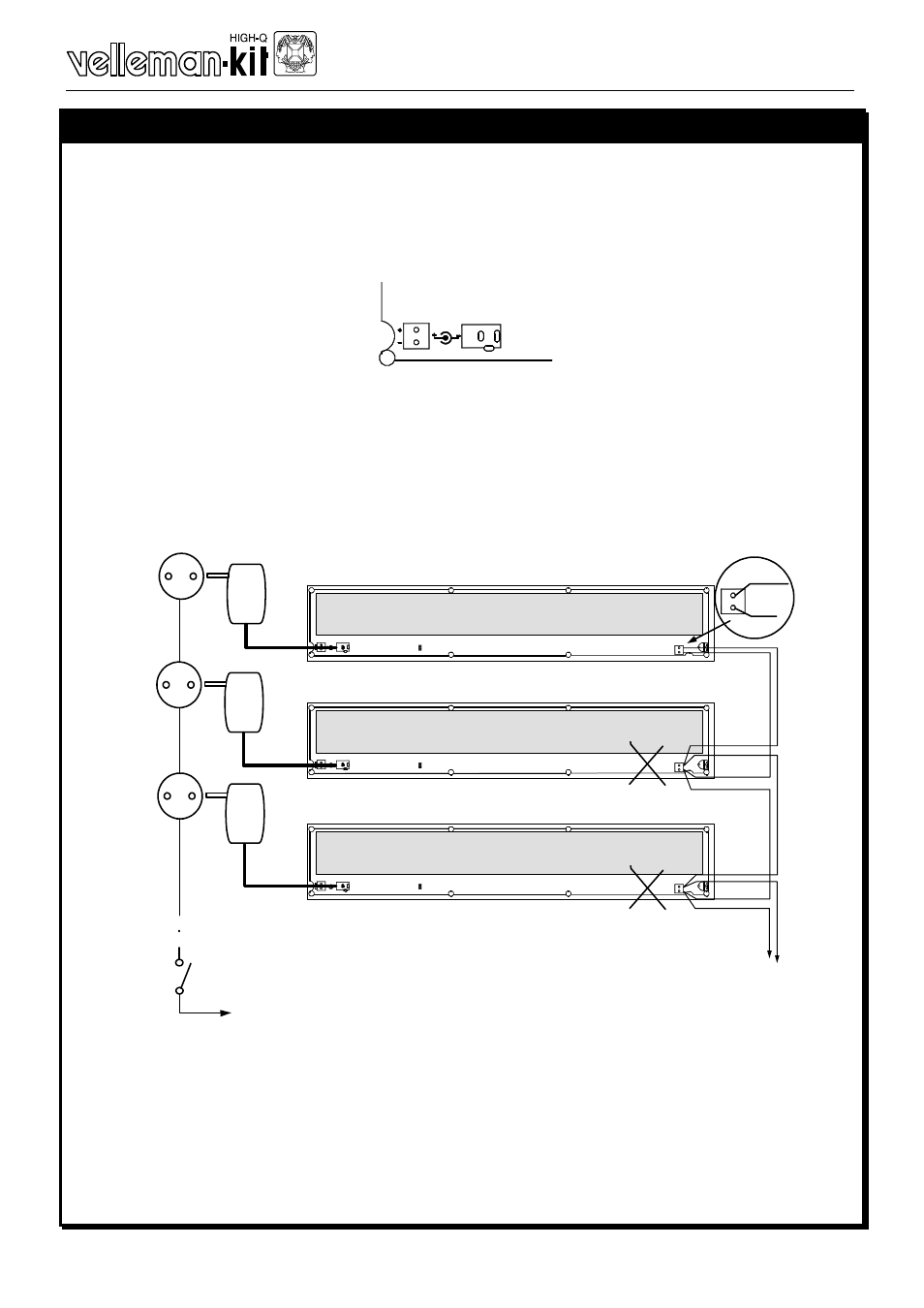
B- Use in a master / slave configuration:
If several units are used together for one advertisement, then it is best to syn-
chronise the effects, this can be done by interconnecting the oscillators of all the
units.
•
Connect the points OSC - I/O together of all units.
•
Connect the points OSC - GND together of all units.
I/O
RV1
+
-
SW
SK1
SK2
GND
OSC
I/O
SPEED
JC
JC OPEN: LIGHT EFFECTS
JC CLOSED: MESSAGE CONTINUE ON
12...28VDC/800mA IN
RV1
+
-
SW
SK1
SK2
GND
OSC
I/O
SPEED
JC
JC OPEN: LIGHT EFFECTS
JC CLOSED: MESSAGE CONTINUE ON
12...28VDC/800mA IN
RV1
+
-
SW
SK1
SK2
GND
OSC
I/O
SPEED
JC
JC OPEN: LIGHT EFFECTS
JC CLOSED: MESSAGE CONTINUE ON
12...28VDC/800mA IN
GND
SK2
GND
OSC
I/O
To MAINS
IC2
IC2
•
Remove IC2 from all units but one, so only in one unit IC2 must be mounted,
this is the master.
•
Connect the power supply of all units, it is preferable to use separate supplies
for each unit.
•
Connect all power supplies to the same mains outlet and switch on the power,
that way all units will receive power at the same time.
FIG 2
FIG1