Service manual reference chart – Spicer ES-165-10H User Manual
Page 3
4. Install washer and retaining ring on the anchor pin. (Same side as grease fitting on the anchor pin). See figure 6.
5. Install washer and a retaining ring on the drum side of the anchor pin. See figure 7.
6. Connect return spring to upper shoe.
7. Position lower shoe for installation on spider (partially installed with shoe roller end disengaged from cam), then
connect return spring to lower shoe.
8. Complete the installation of lower shoe and install anchor pin with grease fitting toward the frame rail side of the
vehicle.
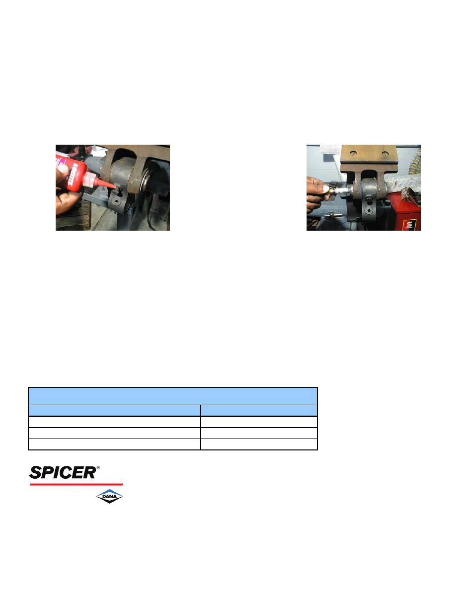
Fig. 8
Fig. 9
9. Install 1/4-24 by 3/8" cap screws and apply Loctite to threads. Tighten cap screws 120-150 in.-lbs. See figure 8.
10. Lubricate anchor pin with high temperature, waterproof grease conforming to NGLI grade #1. Lubricate until grease is
visible between the brake shoe and spider. Wipe off any excess grease. See figure 9.
13. Install dustshield. Secure with cap screws if applicable. Tighten screws to 150-180 in.-lbs.
14. Install brake drums and wheels.
15. Adjust brakes.
Listed below are the Dana service manuals that contain more detailed installation and removal information for the models
referenced in this document. These publications can also be found on our web site at
http://www.
spicerparts.com
Model Series
Manual Number
ES165-6H, ES165-10H
BRSM--0033
Service Manual Reference Chart
For spec’ing or service assistance, call 1-800-
621-8084 24 hours a day, 7 days a week.
Or visit our web site at:
http://www.
spicerparts.com
Dana
Corporation
SHAIS139A
Copyright
Dana
Corporation,
2002
Commercial Vehicle Axle Division
JULY
2002 All
Rights
Reserved. P.O.
Box
Printed in U.S.A.
Toledo, Ohio 43697-0321