Front lift, Front installation diagram – High Lifter Lift Kit for Bombardier 650 Quest User Manual
Page 3
Front Lift
1) Place jack under center of ATV front end and lift until front wheels clear the ground. Be careful to
support ATV properly so that it’s secure, but so that the A-arms and shocks can droop to full
extension.
2) Remove front wheels and shock.
3) Place spacer “E” on the inside of the shock mount, place bracket “A”, with the notch down and
outward over the shock mount. Secure this bracket with a 10x45mm bolt that is provided with the kit.
4) Place bottom of shock inside top of bracket “A”, place spacer “F” between the front of the shock
eyelet and the inside of bracket “A”, securing it with a new 10x45mm bolt from back to front.
5) Next, place bracket “B” on bracket “A” (on the front outside of bracket “A”) securing it with a new
10mm nut.
6) Install bracket “B” on the front of the A-arm and bracket “C” on the rear of the A-arm, then secure
with two ¼” x 1 ¾ ” hex head bolts. Place a ¼” Lock Nut on the ¼” x 1 ¾ ” hex head bolt. Before
tightening all nuts ensure the angle of the shock is at the same original angle.
7) Tighten all bolts to manufacturer specifications.
8) Repeat this procedure for the other side.
9) Install the wheels, torque wheel lugs to manufacturer’s specifications, lower and remove jack. Check
for clearance problems or misalignment.
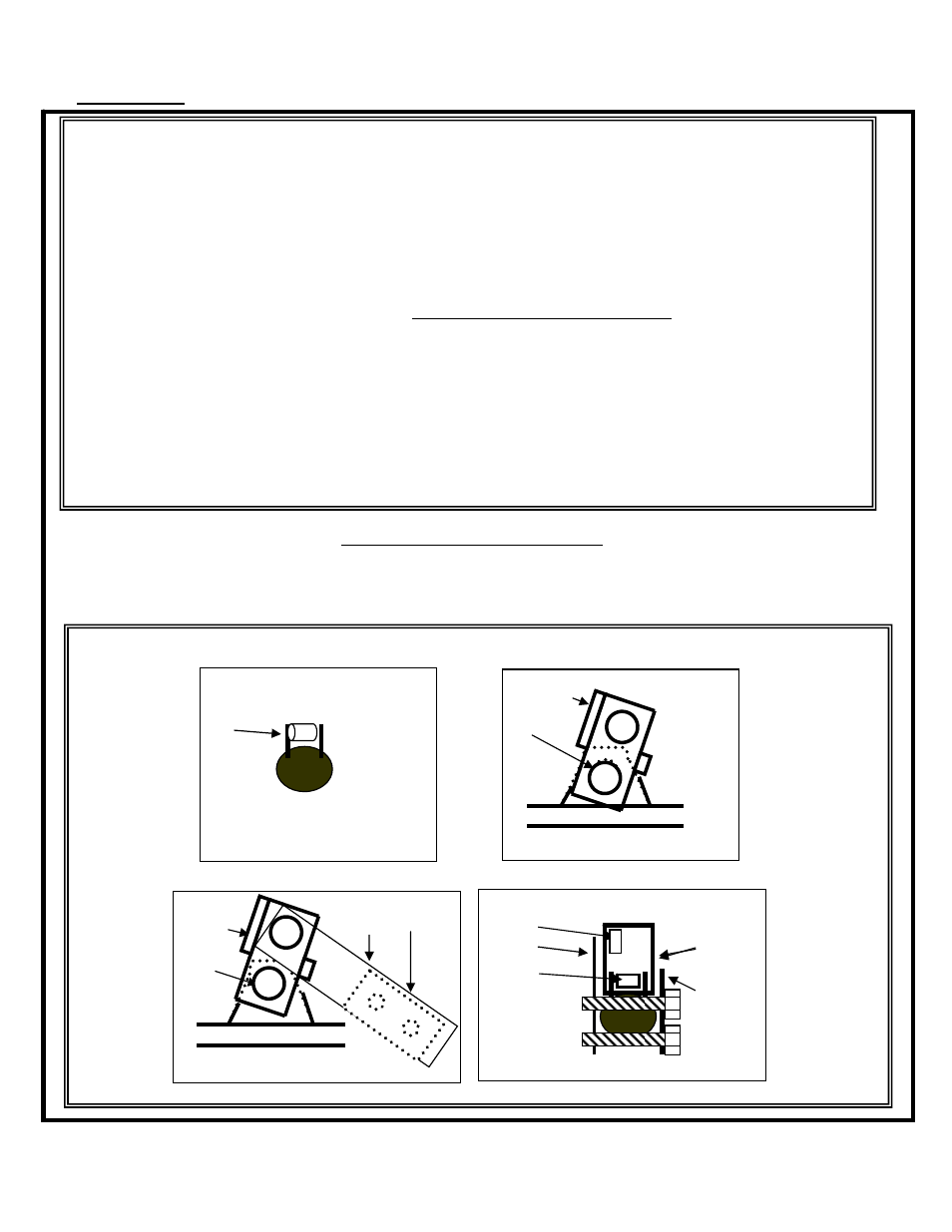
Front Installation Diagram
Note: This diagram is for graphical representation, the actual angles of the shock and mounting
bracket will differ from the diagram.
1
2
A
E
E
4
5
Side View
A
B C
F
B
A
E
E
C
FRONT
REAR