6a 6b – Blue Ox SC9030 User Manual
Page 5
Date 02/07
292-2840
4 of 6
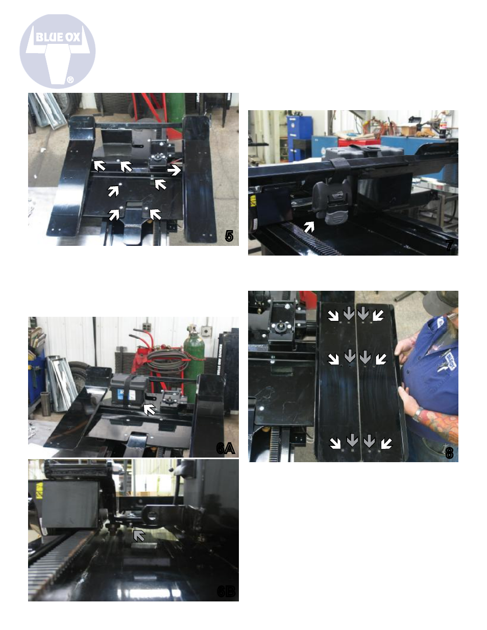
5. Position the holes on the golf cart loader
weldment, so they line up with the cycle slide
head assembly. Insert a 3/8-16x1 1/4” carriage
bolt into each of the seven holes and then tighten
down with a 3/8-16 hex nylon lock nut, using a
9/16” wrench.
5
6. Relocate battery box and tray to area shown
in picture 6A (see white arrow). Run battery
wires from winch to new location of battery and
reattach. Place a clamp loop in area shown
in picture 6B (see grey arrow). Using a 7/16”
wrench, secure it in place with a 1/4-20x1” hex
bolt, 1/4”
at washer and 1/4-20 hex nylon nut
.
6A
6B
7. Using a 5/8” and 11/16” wrench, secure the
cargo buckle set aside in Step 3, to the tab
located near the battery box.
7
8
8. Place adjustable driverside ramp (101-6934)
and passenger side ramp (101-6935) on there
respected side of the golf cart loader weldment.
The holes on the ramp should match up with the
holes on the weldment, according to the golf cart
tire width. For a 43” tire width, see white arrows
on picture above. For a 49” tire width, see grey
arrows on the picture above.