Blue Ox BX88274 User Manual
Blue Ox For the car
BX88274
High Current Fuse ByPass Switch
Installation Instructions
405-0241
Page 1 of 3
2/8/12
ALWAYS match the amperage of the fuse in the Fuse ByPass Switch harness to the fuse removed
from the fuse panel.
NEVER install a fuse with more than a 50 amp rating in the Fuse ByPass Switch harness.
REMOVE any fuse from the Fuse ByPass Switch harness.
BEFORE YOU BEGIN: Consult the owner’s manual for the towed vehicle
to determine which fuse must be removed from the “towed” vehicle’s
under hood fuse box. Remove the large
plastic fuse box cover and remove the high
amperage (e.g. 50 amp) fuse. Confirm that
the colored connectors on the Fuse ByPass
Switch wire (or adapter if supplied) match the pin sizes in the fuse box
location from where you removed the fuse. If your manual requires that
you remove another mini fuse, typically the 15 amp ECM fuse, you will
need an additional mini version of the Fuse ByPass Switch.
Note: A small 5/8” access hole will be drilled into the fuse box cover to complete the installation. It is
recommended that you follow the steps below prior to drilling the access hole.
1. Install the adapter, if supplied. Use a test light or multi-meter set to read 20 volts DC in order to
determine which of the two (2) pins in the fuse box has 12 volts present. Connect the mutli-meter
probe or the clip connector from the test light to a suitable ground connection. Probe the two (2)
terminals with the probe to find the one that shows 12 volts or lights the test light when the probe
is touched to the fuse box terminals. Install the red connector on the Fuse ByPass Switch onto
the 12 volt terminal identified. It is often the one closest to the passenger compartment. Install the
remaining blue connector onto the other terminal in the fuse box.
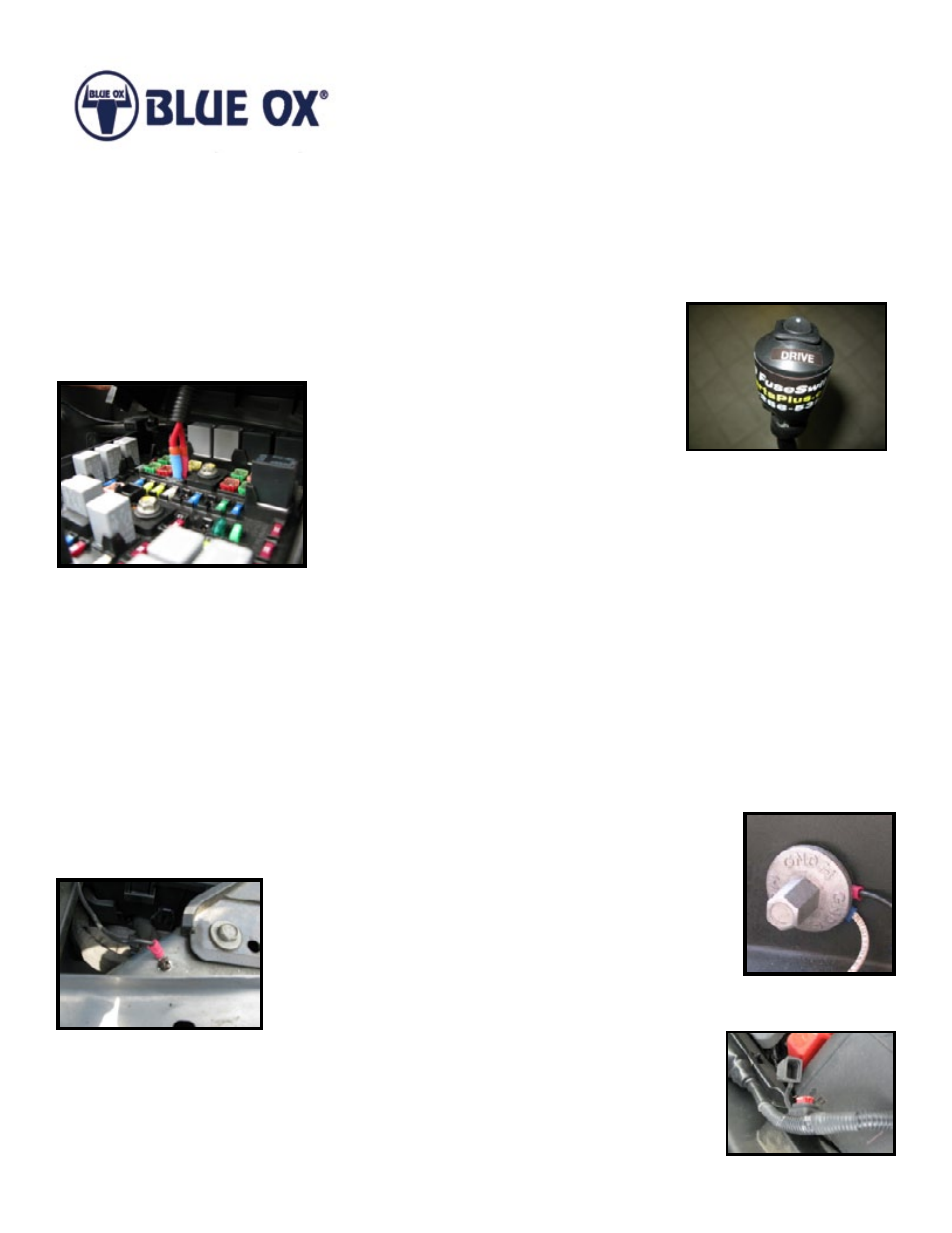
2. Using a portable drill with a Phillips head screwdriver bit, install the ring
connector from the small black fuse holder wire using the supplied self drilling
screw. Locate this screw on the inner fender area close
to the fuse panel so that when installed there is sufficient
wire to lay the Fuse ByPass Switch in a convenient
location near the fuse panel. An alternative is to loosen
the large ground stud to the left of the fuse box and fully
insert the terminal under the ring as shown in the photo, then securely
tighten to retain the ring terminal.
3. Reinstall the 2 amp fuse into the small black fuse holder.
4. Install the larger high current (e.g. 50 amp) fuse into the larger rubber fuse
holder in the Fuse ByPass Switch harness. Gently press it into place and
insure it is fully seated. Cover it with the supplied rubber cap.