English – ASRock P67 Extreme6 User Manual
Page 32
32
ASRock P67 Extreme6 Motherboard
English
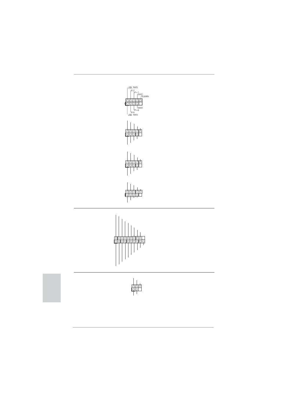
Infrared Module Header
This header supports an
(5-pin IR1)
optional wireless transmitting
(see p.2 No. 39)
and receiving infrared module.
1
IRTX
+5VSB
DUMMY
IRRX
GND
USB 3.0 Header
Besides four default USB 3.0
(19-pin USB3_2_3)
ports on the I/O panel, there is
(see p.2 No. 35)
one USB 3.0 header on this
motherboard. This USB 3.0
header can support two USB
3.0
ports.
1
ID
IntA_P1_D+
IntA_P1_D-
GND
IntA_P1_SSTX+
IntA_P1_SSTX-
GND
IntA_P1_SSRX+
IntA_P1_SSRX-
Vbus
IntA_P2_D+
IntA_P2_D-
GND
IntA_P2_SSTX+
IntA_P2_SSTX-
GND
IntA_P2_SSRX+
IntA_P2_SSRX-
Vbus
1
DUMMY
GND
P+13
P-13
USB_PWR
USB_PWR
GND
P+12
P-12
1
USB_PWR
P-8
GND
DUMMY
USB_PWR
P+8
GND
P-9
P+9
1
USB_PWR
P-10
GND
DUMMY
USB_PWR
P+10
GND
P-11
P+11
USB 2.0 Headers
Besides four default USB 2.0
(9-pin USB6_7)
ports on the I/O panel, there
(see p.2 No. 34)
are four USB 2.0 headers on
this motherboard. Each
USB 2.0 header can support
two USB 2.0 ports.
(9-pin USB8_9)
(see p.2 No. 33)
(9-pin USB10_11)
(see p.2 No. 31)
(9-pin USB12_13)
(see p.2 No. 30)
- H61M-VG3 (48 pages)
- Fatal1ty Z77 Professional-M (245 pages)
- Z87 OC Formula (224 pages)
- B75 Pro3 (205 pages)
- Z77 Extreme3 (169 pages)
- FM2A75 Pro4 (171 pages)
- Z77 Pro4-M (230 pages)
- H61M-GE (181 pages)
- B85 Pro4 (163 pages)
- H77 Pro4-M (230 pages)
- Z77 Extreme11 (241 pages)
- Z77M (210 pages)
- H67M-GE__HT (271 pages)
- H81M (163 pages)
- A75 Pro4 (282 pages)
- E350M1 (144 pages)
- Z87 Pro4 (163 pages)
- 990FX Extreme4 (281 pages)
- FM2A75 Pro4-M (164 pages)
- FM2A55M-DGS (138 pages)
- X79 Extreme3 (204 pages)
- 990FX Extreme3 (182 pages)
- P67 Extreme4 (304 pages)
- A55 Pro3 (190 pages)
- Z87 Extreme3 (164 pages)
- FM2A75M-ITX R2.0 (146 pages)
- H61M-GS (162 pages)
- AD2500B-ITX (143 pages)
- E350M1__USB3 (144 pages)
- Fatal1ty Z77 Performance (219 pages)
- H87 Pro4 (150 pages)
- H61DE__S3 (164 pages)
- X79 Extreme4-M (229 pages)
- Fatal1ty Z68 Professional Gen3 (317 pages)
- P67 Extreme4 Gen3 (304 pages)
- H77M-ITX (190 pages)
- Z87 Extreme6__ac (196 pages)
- H61M-DPS (51 pages)
- X79 Extreme11 (270 pages)
- H61iCafe (158 pages)
- 980DE3__U3S3 (151 pages)
- Fatal1ty Z77 Professional (243 pages)
- Z68M__USB3 (177 pages)
- H81M-DGS (57 pages)
- Z75 Pro3 (192 pages)