English – ASRock Z77 Extreme11 User Manual
Page 29
ASRock Z77 Extreme11 Motherboard
29
English
Power LED Header
(3-pin PLED1)
(see p.2, No. 22)
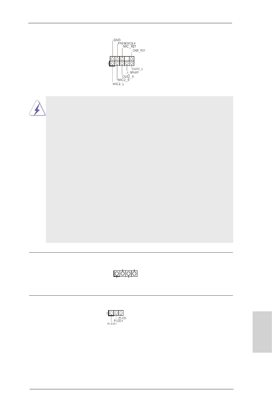
Front Panel Audio Header
(9-pin HD_AUDIO1)
(see p.2, No. 38)
This is an interface for the
front panel audio cable that
allows convenient connec-
tion and control of audio
devices.
Chassis Speaker Header
(4-pin SPEAKER1)
(see p.2, No. 23)
Please connect the chassis
speaker to this header.
Please connect the chassis
power LED to this header
to indicate system power
status. The LED is on when
the system is operating. The
LED keeps blinking in S1/S3
state. The LED is off in S4
state or S5 state (power off).
1
+5V
DUMMY
DUMMY
SPEAKER
1. High Definition Audio supports Jack Sensing, but the panel wire on
the chassis must support HDA to function correctly. Please follow
the instructions in our manual and chassis manual to install your
system.
2. If you use an AC’97 audio panel, please install it to the front panel
audio header by the steps below:
A. Connect Mic_IN (MIC) to MIC2_L.
B. Connect Audio_R (RIN) to OUT2_R and Audio_L (LIN) to
OUT2_L.
C. Connect Ground (GND) to Ground (GND).
D. MIC_RET and OUT_RET are for HD audio panel only. You don’t
need to connect them for AC’97 audio panel.
E. To activate the front mic.
For Windows
®
8 / 8 64-bit / 7 / 7 64-bit / Vista
TM
/ Vista
TM
64-bit OS:
Go to the “FrontMic” Tab in the Realtek Control panel. Adjust
“Recording Volume”.