Deutsch, Asrock h77 pro4-m motherboard, Anschluss eines druckerport – ASRock H77 Pro4-M User Manual
Page 49: Ports am e/a-panel, Usb 2.0-ports an den, Usb 2.0-ports unterstützt, Optionales, drahtloses sende, Und empfangs-infrarotmodul
49
ASRock H77 Pro4-M Motherboard
Deutsch
1
AFD#
ERROR#
PINIT#
GND
SLIN#
STB#
SPD0
SPD1
SPD2
SPD3
SPD4
SPD5
SPD6
SPD7
ACK#
BUSY
PE
SLCT
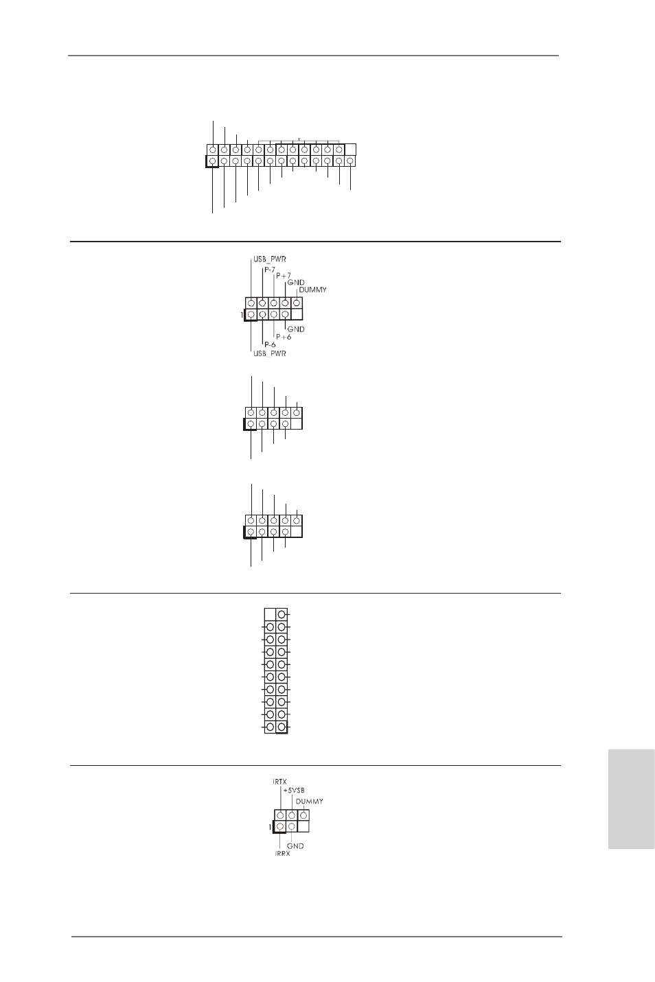
Druckerport-Anschlussleiste
Dies ist eine Schnittstelle zum
(25-pol. LPT1)
Anschluss eines Druckerport-
(siehe S.2 - No. 28)
Kabels, mit dem Sie passende
Drucker auf einfache Weise
anschließen können.
USB 3.0-Header
Neben zwei Standard-USB
(19-pol. USB3_12_13)
3.0-Ports am E/A-Panel
(siehe S.2 - No. 9)
befindet sich ein USB 3.0-
Header an diesem
Motherboard. Dieser USB 3.0-
Header kann zwei USB 3.0-
Ports unterstützen.
USB 2.0-Header
Zusätzlich zu den vier üblichen
(9-pol. USB_6_7)
USB 2.0-Ports an den
(siehe S.2 - No. 25)
I/O-Anschlüssen befinden sich
drei USB 2.0- Anschlussleisten
am Motherboard. Pro USB 2.0-
Anschlussleiste werden zwei
(9-pol. USB_8_9)
USB 2.0-Ports unterstützt.
(siehe S.2 - No. 24)
(9-pol. USB_10_11)
(siehe S.2 - No. 23)
Infrarot-Modul-Header
Dieser Header unterstützt ein
(5-pin IR1)
optionales, drahtloses Sende-
(siehe S.2 - No. 19)
und Empfangs-Infrarotmodul.
IntA_P13_D
DUMMY
IntA_P13_D
GND
IntA_P13_SSTX
GND
IntA_P13_SSTX
IntA_P13_SSRX
IntA_P13_SSRX
Vbus
Vbus
Vbus
IntA_P12_SSRX
IntA_P12_SSRX
GND
IntA_P12_SSTX
IntA_P12_SSTX
GND
IntA_P12_D
IntA_P12_D
1
USB_PWR
P-8
GND
DUMMY
USB_PWR
P+8
GND
P-9
P+9
1
USB_PWR
P-10
GND
DUMMY
USB_PWR
P+10
GND
P-11
P+11