Installation and connections, Connections and system wiring diagram, Precautions – Alpine TUE-T150DV User Manual
Page 19: Installation, S-video output, Power status led, Erasing the eeprom (reset to factory default), Iva-d106r, Hce-c200r
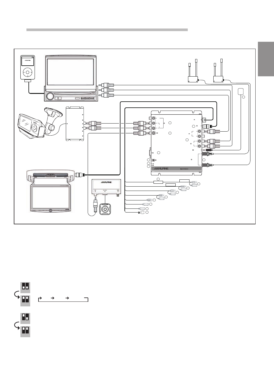
Installation and Connections
Connections and System Wiring Diagram
3
2
6
4
1
5
10
11
12
13
15
17
18
Mode switches for starting software download and
erasing the EEPROM
Reset button
Camera Input
7
S-Video output
8
Power status LED
9
External IR sensor
1 x RCA A/V auxiliary input
Antenna input socket (F-plug/female) with
integrated 5V/30mA power supply.
1 x RCA A/V output & front video output
Battery lead (yellow)
Connect to a live terminal in the fuse block connecting to
the car battery (bypassing the ignition switch).
Fuse holder (3.0A)
Switched power lead (Ignition) (red)
Connect to an accessory terminal in the fuse block.
Parking brake lead (yellow/blue)
Connect to parking brake or metallic body or chassis
of the car.
Remote control input/output lead (white/brown - male plug)
14
Reverse Lead (orange/white)
Co
Use when connecting a rear view camera.
Connect to a Reverse gear activated 12 volt signal.
The camera signal is switched to ghe front video output only.
nnect to remote control lead of monitor.
16
Remote control input/output lead (white/brown - female plug)
Connect to remote control lead of KCE-415i (optional).
Power antenna remote output (+12V/150mA) lead (blue)
Ground lead (black)
Connect to metallic body or chassis of the car.
21-EN
-Selecting the video output format (factory default is PAL):
1. Turn TUE-T150DV on
2. Set both DIP switches to down position
3. Select the video system by pressing the RESET button
4. Set both DIP switches to up position!
-Erasing the EEPROM (reset to factory default):
1. Turn TUE-T150DV on
2. Switch DIP1 to the up position and DIP2 to the down position
3. Press the RESET button and wait for 10 sec. until the
deletion is finished
4. Set both DIP switches to up position!
5. Press once again the RESET button
PAL
NTSC
SECAM
PAL
NTSC
SECAM
1 2
1 2
1 2
1 2
ANTENNA INPUT
1
2
RESET
MODE
CAMERA IN
FRONT VIDEO
OUTPUT
AUX IN
AUDIO
VIDEO
R
L
S-VIDEO
POWER
EXT.
REMOTE EYE INPUT
POWER SUPPLY
DIGITAL TV-TUNER UNIT
TUE-T150DV
POWER
S-VIDEO
IPOD
C.VIDEO
LEFT
RIGHT
C.VIDEO
S-VIDEO
VIDEO INTERFACE ADAPTER
KCE-415i
iPod
MENU
POWER
SOURCE
TA
RDS
MOBILE MEDIASTATION
IVA-W200Ri
Red
White/Brown
Black
Yellow
Red
Yellow/Blue
White/Brown
Blue
BATT
ACC
Black
White/Brown
Orange/White
ANTENNA INPUT
1
2
RESET
MODE
CAMERA IN
FRONT VIDEO
OUTPUT
AUX IN
AUDIO
VIDEO
R
L
S-VIDEO
POWER
EXT.
REMOTE EYE INPUT
POWER SUPPLY
DIGITAL TV-TUNER UNIT
TUE-T150DV
POWER
S-VIDEO
IPOD
C.VIDEO
LEFT
RIGHT
C.VIDEO
S-VIDEO
VIDEO INTERFACE ADAPTER
KCE-415i
POWER
S-VIDEO
IPOD
C.VIDEO
LEFT
RIGHT
C.VIDEO
S-VIDEO
VIDEO INTERFACE ADAPTER
KCE-415i
iPod
MENU
iPod
MENU
POWER
SOURCE
TA
RDS
MOBILE MEDIASTATION
IVA-W200Ri
POWER
SOURCE
TA
RDS
MOBILE MEDIASTATION
IVA-W200Ri
Red
White/Brown
Black
Yellow
Red
Yellow/Blue
White/Brown
Blue
BATT
ACC
Black
White/Brown
Orange/White
Yellow
Red
Yellow/Blue
White/Brown
Blue
BATT
ACC
Black
White/Brown
Orange/White
1
2
3
4
5
6
7
8
9
10
11
12
13
14
15
16
17
18
12
17
15
20-EN
Precautions
Be sure to disconnect the cable from the (–) battery
post before installing your TUE-T150DV. This will reduce
any chance of damage to the unit in case of a shortcircuit.
• Be sure to connect the color coded leads according to
the diagram. Incorrect connections may cause the unit
to malfunction or damage the vehicle's electrical
system.
• When making connections to the car’s electrical
system, be aware of the factory installed components
(e.g. on-board computer). Do not tap into these leads to
provide power for this unit. When connecting the
TUE-T150DV to the fuse box, make sure the fuse for the
intended circuit of the TUE-T150DV has the appropriate
amperage. Failure to do so may result in damage to the
unit and/or the vehicle. When in doubt, consult your
ALPINE dealer.
• The TUE-T150DV uses female RCA-type jacks for
connection to other units (e.g. amplifier) having RCA
connectors. You may need an adaptor to connect other
units. If so, please contact your authorized ALPINE
dealer for assistance.
Installation
Installing TV TUNER
This TV TUNER can be placed inside the trunk,
on the kick panel of the front passenger's seat or
underdash. However, to avoid unnecessary
signal wiring, it is better to mount the TV TUNER
as close as possible to the Display.
DO NOT MOUNT THE UNIT IN LOCATIONS
THAT WILL BE IN THE VICINITY OF MOISTURE
OR EXTREME HEAT (such as the engine
compartment).
EN
21-EN
IVA-D106R
Yellow
Red
Yellow/Blue
White/Brown
Blue
BATT
ACC
Black
White/Brown
Orange/White
iPod
MENU
P
O
W
E
R
M
IC
R
-A
U
D
IO
-L
D
IS
P
L
A
Y
A
N
T
E
N
N
A
IN
P
U
T
a
B
L
A
C
K
B
IR
D
P
M
D
-B
20
0 D
O
C
K
IN
G
A
D
A
P
T
O
R
P
M
D
-D
O
K
2
HCE-C200R
1
8
9
7
5
6
4
3
10
12
11
13
14
15
16
17
18
19
2
REMOTE EYE INPUT
DIGITAL TV-TUNER UNIT
VIDEO
R
L
VIDEO OUT
AUDIO
S-VIDEO
POWER
RESET
MODE
RS232
CAMERA IN
AUX IN
POWER SUPPLY
REAR
FRONT
1
2
ANTENNA INPUT
AUDIO OUT
L
R
TUE-T150DV
Antenna input socket (F-plug/female) with integrated 5V/31mA
11
power supply1
1 x RCA A/V output & front video output
21
S-Video output
31
1 x RCA A/V auxiliary input
41
Camera Input
51
RS232
61
9pin D_SUB Software update
Mode switches for starting software download and erasing the
71
EEPROM
-Selecting the video output format (factory default is PAL):
Turn TUE-T150DV on
i.
Set both DIP switches to down position
ii.
Select the video system by pressing the RESET button
iii.
PAL
NTSC
SECAM
PAL
NTSC
SECAM
Set both DIP switches to up position!
iv.
-Erasing the EEPROM (reset to factory default):
Turn TUE-T150DV on
i.
Switch DIP1 to the up position and DIP2 to the down position
ii.
Press the RESET button and wait for 10 sec. until the deletion is
iii.
finished
Set both DIP switches to up position!
iv.
Press once again the RESET button!
v.
Reset button
81
Power status LED
91
External IR sensor
111
Battery lead (yellow)
111
Connect to a live terminal in the fuse block connecting to the car
battery (bypassing the ignition switch).
Fuse holder (311A)
121
Switched power lead (Ignition) (red)
131
Connect to an accessory terminal in the fuse block.
Parking brake lead (yellow/blue)
141
Connect to parking brake or metallic body or chassis of the car.
Reverse Lead (orange/white)
151
Use when connecting a rear view camera.
Connect to a Reverse gear activated 12 volt signal.
The camera signal is switched to ghe front video output only.
Remote control input/output lead (white/brown - male plug)
161
Connect to remote control lead of monitor.
Remote control input/output lead (white/brown - female plug)
171
Connect to remote control lead of KCE-415i (optional).
Power antenna remote output (+12V/151mA) lead (blue)
181
Ground lead (black)
191
Connect to metallic body or chassis of the car.
1 2
1 2
1 2
1 2