ACU-RITE ENC 150 (Old Style) User Manual
Page 18
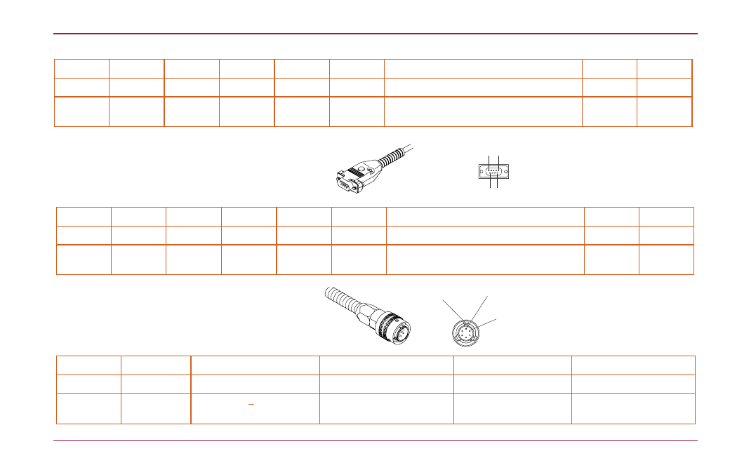
Pin 1
Pin 2
Pin 3
Pin 4
Pin 5
Pin 6
Pin 7
Pin 8
Pin 9
White
Green
Yellow
Blue
Red
N/C
Brown
Pink
Gray
Ground
Channel
A+
Channel
A-
Channel
B+
Channel
B-
N/C
Vcc, + 5.0
± 0.1 VDC @ 80mA max.
Channel
R+
Channel
R-
Pin 1
Pin 2
Pin 3
Pin 4
Pin 5
Pin 6
Pin 7
Pin 8
Pin 9
N/C
Green
Yellow
Blue
Red
White
Brown
Pink
Gray
N/C
Channel
A+
Channel
A-
Channel
B+
Channel
B-
Ground
Vcc, + 5.1
± 0.1 VDC @ 140mA max.
Channel
R+
Channel
R-
Pin A
Pin B
Pin C
Pin D
Pin E
Pin F
Green
Blue
Brown
White
Drain
Pink
Channel A
Channel B
Vcc, +5.1 + 0.1 VDC @
140mA max.
Common (power supply and
signal return)
Shield, reading head
casting ground
Channel R (Reference
Mark)
Digital Differential
Digital single ended
Analog Differential
1
6 9
5
A
B
Large key
ENC 150
Output Signals and Pin-Outs
17
ACU-RITE
®
This manual is related to the following products: