ACU-RITE ENC 150 (New Style) User Manual
Page 15
• Route the cables with slack loops to allow for axis motion.
• Secure excess cable by fastening with clips or ties.
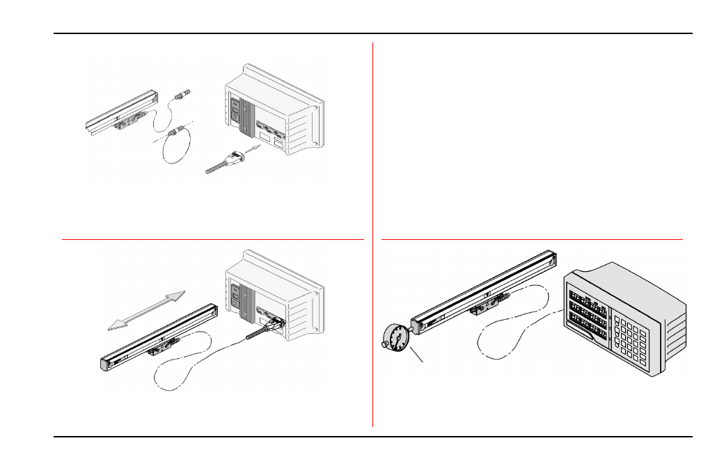
• Attach the linear encoder connectors to the readout.
• Move the axis and compare the display to the movement.
• Move the axis 20mm (.79”) to check reference mark operation.
• Zero the display and indicator.
• Move axis to the end of it’s travel return to dial zero.
• Readout should read zero ± 1 count.
13
ACU-RITE
®
ENC150
Checking Your Installation
Place dial indicator at the end of the moving
component (scale assembly or reading head).
Repeatability Test
Readout
Counting Test
Connecting
Counting Test:
• Configure the readout’s encoder and display resolution (see
manual).
• Move the axis and compare the display to the movement.
• Configure readout for sensing reference marks.
• Move each axis a minimum of 20mm (axis display should zero).
Repeatability Test:
• Locate an indicator on one end of the encoder and zero the readout
and indicator.
• Move the axis through the full travel and return to dial zero.
• Readout should read zero ± 1 count.
These steps will confirm proper operation of your installation. The
counting Test confirms proper electrical operation. the Repeatability
Test checks the installation integrity
Secure excess
cable
Provide slack
loops
Attach connector