ACU-RITE ENC 150 (New Style) User Manual
Page 13
These steps apply to all spar mounting conditions.
• ACU-RITE bracket kit instructions supercede this
section.
• Adjust drill depths and fastener lengths as required.
• When instructed on page 12: Adjust the leveling set screws
as follows:
1. Insert, but do not tighten 8-32 (M4) reading head screws.
2. Place a .001”-.003” shim between the leveling set screws and
mounting surface.
3. Adjust each set screw until a slight drag is felt on the shim.
4. Evenly tighten the 8-32 (M4) reading head mounting
screws.
• Contact your Authorized ACU-RITE Distributor should you
require additional assistance.
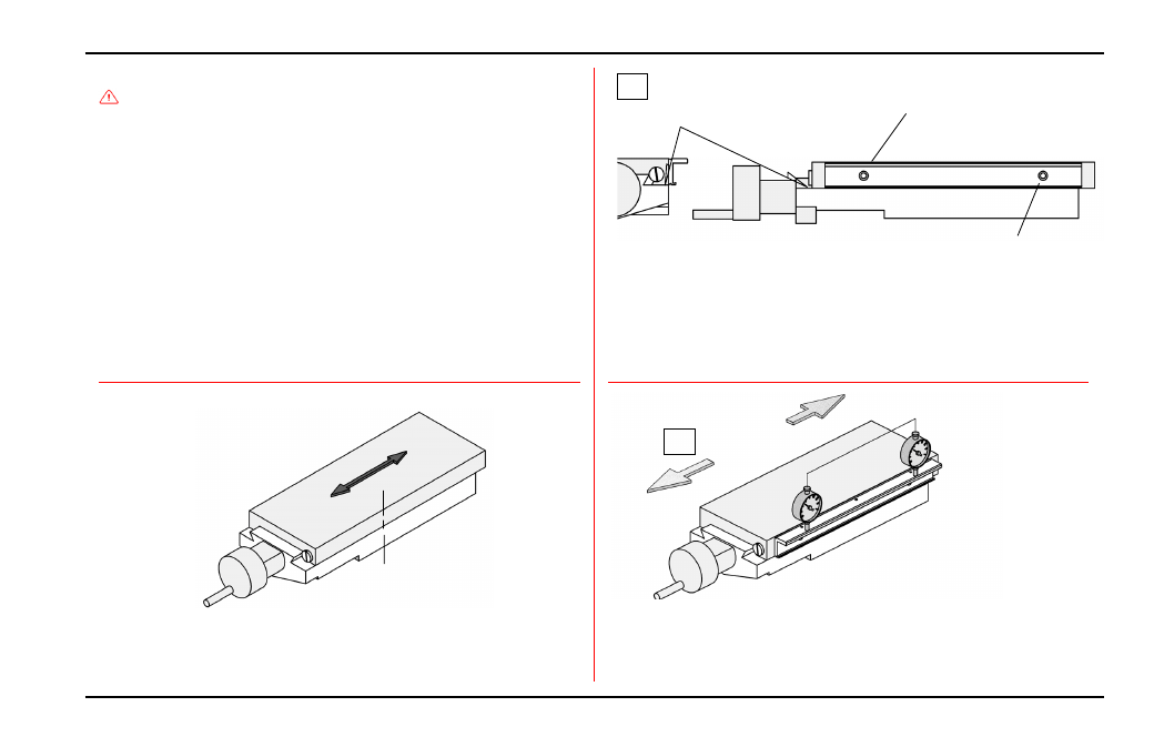
• Move the axis to its center of travel.
• Mark the axis for quick return to center.
• Determine encoder cable exit direction and adjust (see page 3).
• Drill / tap the first end mounting hole / attach the spar.
• Align to within .010” TIR. to -A-, drill / tap second end hole.
• Attach the spar / align to within .010” TIR. to -A-.
• Locate the spar with the underside flush with the axis parting line.
• Mark one end mounting hole location.
11
ACU-RITE
®
ENC150
Spar Installation Procedure
Center
mounting
axis
Mark
center of
axis
CL
Align to within .010” TIR of -A-
Align top of spar to
within .015” of -A-
-A- = Axis travel
Axis parting line
-A- = Axis travel
1/4-20 x 1/2” BHCS &
Flat washer .017” thk.
End mounting hole (typical)