Figure 2. remote switch front view, Figure 3. buzzer, Figure 4. battery pack assembly – ACR&Artex G406-4 ELT User Manual
Page 29
25-62-21
Page 29 of 86
JUL 31/12
ACR ELECTRONICS, INC / ARTEX PRODUCTS
DESCRIPTION, OPERATION, INSTALLATION AND MAINTENANCE MANUAL
G406-4 (453-5012)
(2)
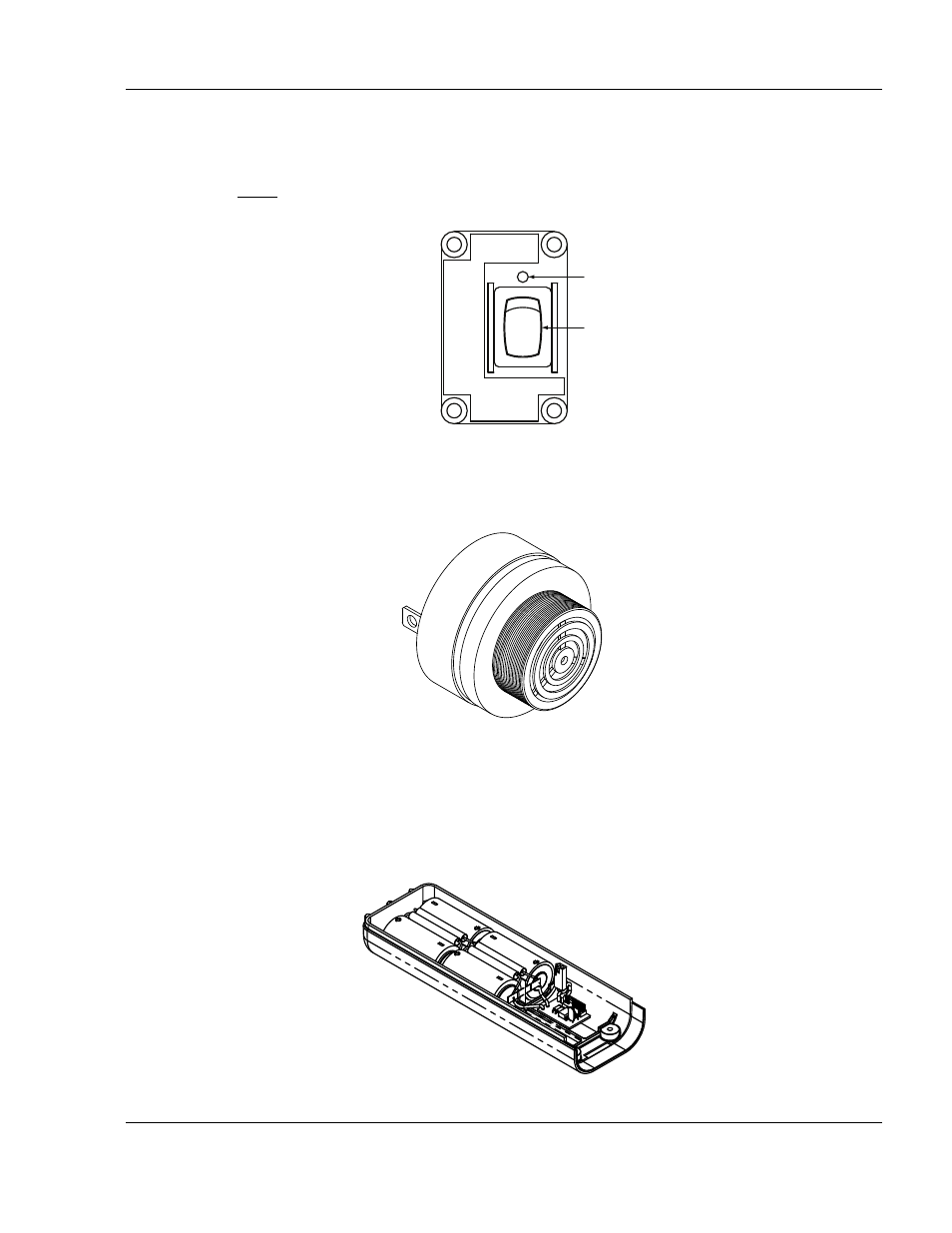
The cockpit-mounted remote switch assembly is comprised of an ELT status LED and control
switch and allows an operator to manually turn the ELT on (i.e., activate) for testing and reset
(i.e., deactivate) the ELT. See "Figure 2. Remote Switch Front View".
NOTE: The ELT CANNOT be disarmed or disabled from the cockpit. Cockpit operation is
limited to deactivating or manually activating the ELT.
Figure 2. Remote Switch Front View
(3)
The buzzer (i.e., horn) provides an audible alert when the ELT is active. See "Figure 3.
Figure 3. Buzzer
(4)
The battery pack for the G406-4 ELT consists of four “D” size lithium manganese dioxide cells
connected in series. In an effort to increase the safety of the battery pack, a number of
features were designed into the battery pack. To prevent the cells from being charged, diodes
are connected across each cell and fuses are connected to the output. See "Figure 4. Battery
Figure 4. Battery Pack Assembly
ARTEX
ON
ARM
Press ON
Wait 1 Second
Press ARM
EMERGENCY USE ONL
Y
Test/Reset
ELT
LED
SWITCH