Helicopter installations - special considerations, A. background, B. recommendations – ACR&Artex ME406 ACE ELT User Manual
Page 74: Figure 25 elt orthogonal axes
ARTEX PRODUCTS / ACR ELECTRONICS, INC
DESCRIPTION, OPERATION, INSTALLATION AND MAINTENANCE MANUAL
ME406 (453-6603), ME406HM (453-6604)
25-62-30
Page 74 of 84
May 03/13
TASK 25-62-30-410-803
9. Helicopter Installations - Special Considerations
SUBTASK 25-62-30-990-001
A. Background
(1)
There are few guidelines, aside from experience, regarding the best way to mount an ELT in
helicopters.
(2)
Before the availability of multi-axis G-switch modules, manufacturers advised installing ELTs
with the sensitive axis pointing approximately 45° downward from the normal forward
direction of flight.
(a)
This mounting attitude was adapted due to a combination of the directional sensing
limitations of a single-axis G-switch and the flight characteristics of helicopters.
(b)
Mounting the ELT in this attitude and orientation is currently specified by CAR, Part 5,
Subpart 551.104.
(c)
Experience has indicated this mounting angle tends to preload the G-switch and
“nuisance” activation can occur as a result of severe aircraft maneuvers, and abrupt
takeoffs and landings.
(3)
ACR Electronics does not recommend installing ELTs designed with a single-axis G-switch in
helicopters due the limitations and issues cited above.
SUBTASK 25-62-30-990-002
B. Recommendations
(1)
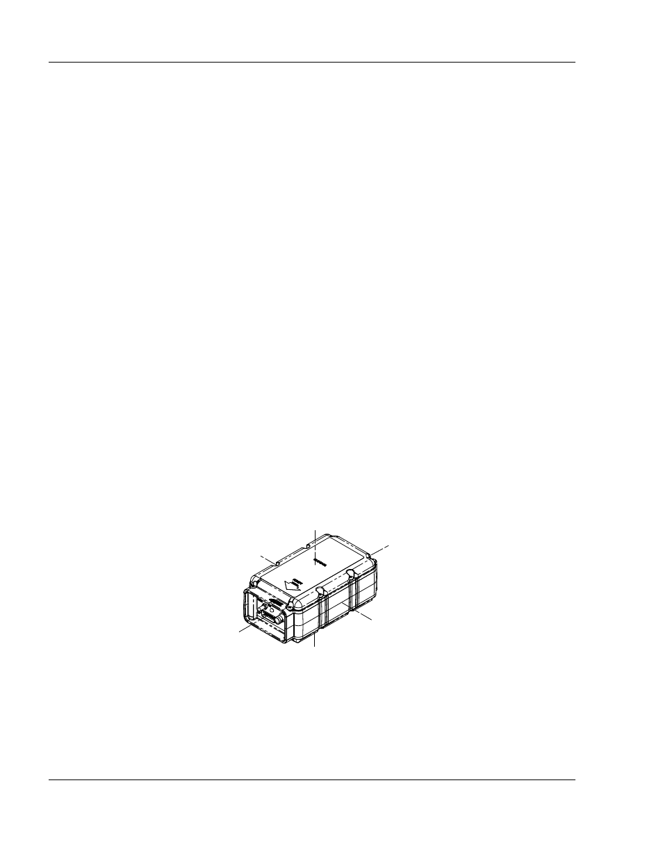
ACR Electronics recommends installation of the ME406HM ELT in helicopters. The ME406HM
ELT is equipped with a 5-axis G-switch module in addition to the usual primary G-switch,
which is oriented to the direction of flight. See Figure 25 ELT Orthogonal Axes.
Figure 25 ELT Orthogonal Axes
(2)
The six-axis coverage of the ME406HM design accommodates the flight characteristics of
helicopters, while allowing “normal” installation and eliminating or significantly reducing
“nuisance” ELT activations.
+Z
-Z
+X
-X
-Y
+Y