Toggle switch wiring, Vdc installation – ACR&Artex 2-Wire ELT__RSWT Interface User Manual
Page 18
ACR Electronics, Inc. 570-0049 Revision B
The information within this document and any attached materials is proprietary and confidential
and is not to be disseminated, distributed, or otherwise conveyed throughout your organization to
employees without a need for this information or to any third parties without the express written
permission of ACR Electronics, Inc.
Page 18 of 30
7.2
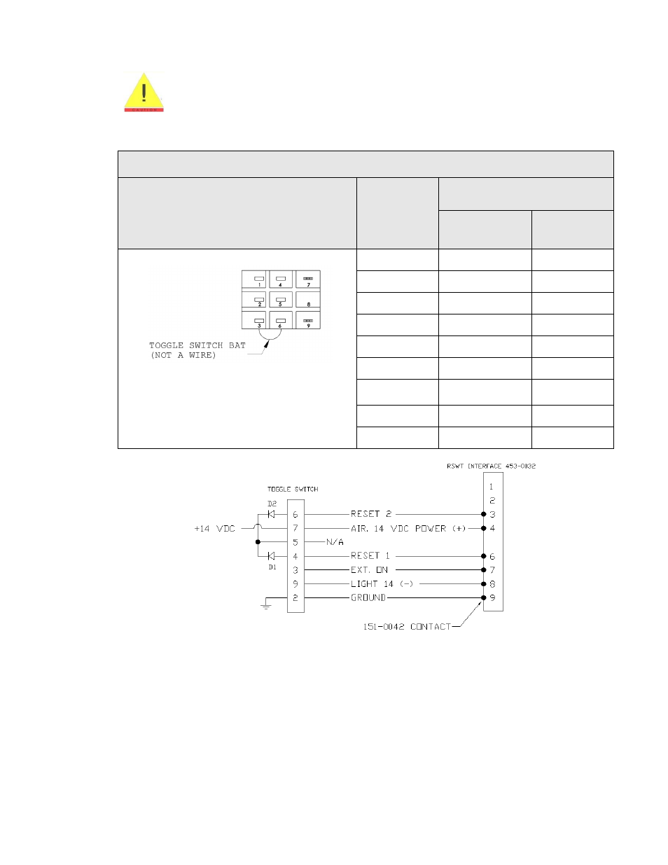
140-3349 TOGGLE SWITCH WIRING (14 VDC INSTALLATION)
Improperly wiring the aircraft power to the D-sub will irreversibly damage
the interface.
7.2.1
Solder the wires from the 453-0032 interface to the toggle switch according to the following
information for 14 VDC aircraft power:
Table 7: 14 VDC Aircraft Power
CONTACT LOCATION
TOGGLE
SWITCH
CONTACT #
453-0032 INTERFACE
DESCRIPTION
CONTACT #
1
N/A
N/A
2
Ground
9
3
Ext. On
7
4
Reset 1
6
5
N/A
N/A
6
Reset 2
3
Diodes not shown
7
Aircraft Power
(14 VDC)
4
8
N/A
N/A
9
Light 14 (-)
8
Figure 4: 453-0032 Wiring Diagram For 14 VDC Installation
NOTE: The toggle switch is not grounded to the ELT, so the system works for metallic and
composite aircrafts when the beacon and the toggle are installed far apart.