Figure 2: tyco crimping tool, Figure 3: crimp overview – ACR&Artex 2-Wire ELT__RSWT Interface User Manual
Page 13
ACR Electronics, Inc. 570-0049 Revision B
The information within this document and any attached materials is proprietary and confidential
and is not to be disseminated, distributed, or otherwise conveyed throughout your organization to
employees without a need for this information or to any third parties without the express written
permission of ACR Electronics, Inc.
Page 13 of 30
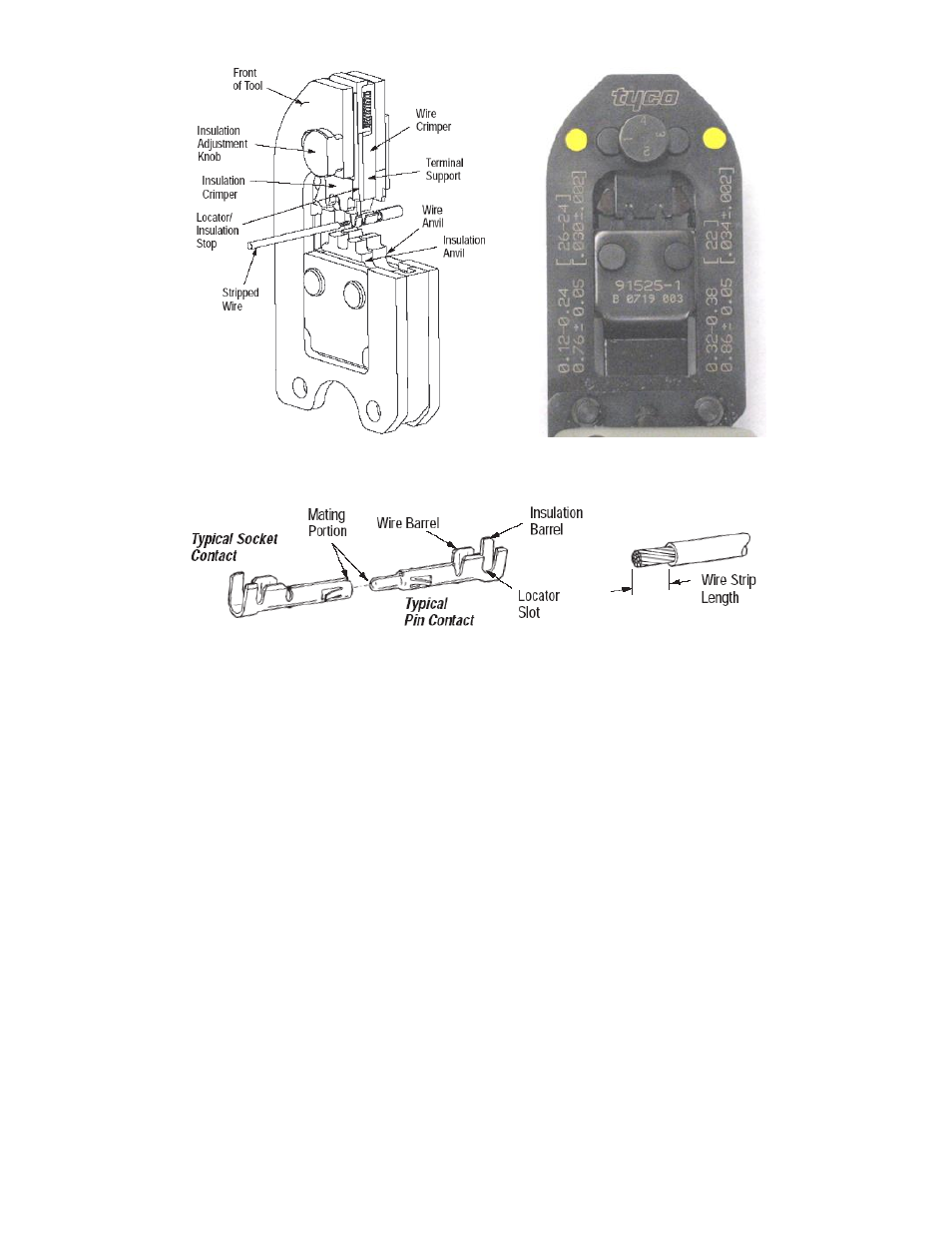
Figure 2: Tyco Crimping Tool
Figure 3: Crimp Overview
4.2.11 Hold the contact in this position and squeeze the tool handles together until the insulation anvil
starts entry into the insulation crimper (usually two ratchet clicks). Do NOT deform the insulation
barrel or wire barrel.
4.2.12 Insert a properly stripped wire through the locator slot and into the wire barrel of the contact until
the insulation butts against the locator/insulation stop.
4.2.13 Hold the wire in place and crimp the contact to the wire by squeezing the tool handles together
until the ratchet releases.
4.2.14 Allow the tool handles to open fully and remove the crimped contact from the tool.
4.2.15 Check the crimp height with a micrometer and ensure that it meets dimension 0.0300 to 0.0345
(±0.0020).
4.2.16 Position the contact in the appropriate contact cavity of the D-sub (150-0022) based on the wiring
diagrams mentioned in the appropriate section of this document depending if the 453-0032 or
453-0041 is installed.
4.2.17 Push the contact inside the cavity using the insertion/removal tool 91067-2 or equivalent (20-24
AWG), or 91285-1 or equivalent (24-28 AWG).
4.2.18 Ensure that the contact is locked in the cavity.
4.2.19 Repeat the previous steps for all the wires required in the D-sub connector attaching to an
interface.