ACR&Artex 2-Wire ELT__RSWT Interface User Manual
Page 15
ACR Electronics, Inc. 570-0049 Revision B
The information within this document and any attached materials is proprietary and confidential
and is not to be disseminated, distributed, or otherwise conveyed throughout your organization to
employees without a need for this information or to any third parties without the express written
permission of ACR Electronics, Inc.
Page 15 of 30
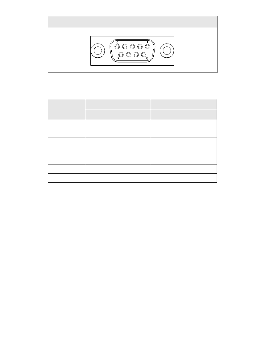
Table 4: ELT Interface 453-0041 Front View
Example:
The following information highlights the wiring of the ME406 ELT series to the ELT interface 453-
0041:
DESCRIPTION
ME406 SERIES ELT
453-0041 ELT INTERFACE
PIN OUT
PIN OUT
Light
2
6
Reset 1
6
3
Reset 2
13
4
External ON
14
8
Ground
7
7 and 9
Horn power
8
5
Horn ground
7 or aircraft ground
7
5.1.4
The wires for the interface 453-0041 are crimped and inserted inside the D-sub connector 150-
0022 using the same procedure highlighted in the
“Cable Harness” section.
NOTE: Do not close the backshell if the two communication wires have not been installed yet.
Refer to section
“453-0032 wiring to 453-0041” in this document to complete the wiring
across the interfaces.
5.1.5
Install the D-sub connector inside a backshell (151-0006) at the completion of the crimping
process.
5.1.6
Secure the strain relief using the screws provided in the backshell kit.
5.1.7
Install the thumbscrews and close the backshell with the screws.
5.1.8
Attach the backshell to the interface 453-0041 using a torque between 1.5 and 2.0 in-lb (.7 to .22
Nm) at the completion of the entire wiring process.
NOTE: Accidently attaching the interface 453-0032 to the backshell instead of the 453-0041 does
not harm the ELT, the toggle switch 140-3349, or any of the interfaces. The outcome is
that the ELT cannot be activated remotely through the toggle switch 140-3349.