0041 wiring to elt, Instructions – ACR&Artex 2-Wire ELT__RSWT Interface User Manual
Page 14
ACR Electronics, Inc. 570-0049 Revision B
The information within this document and any attached materials is proprietary and confidential
and is not to be disseminated, distributed, or otherwise conveyed throughout your organization to
employees without a need for this information or to any third parties without the express written
permission of ACR Electronics, Inc.
Page 14 of 30
4.2.20 Install the D-sub connector inside a backshell (151-0006).
4.2.21 Secure the strain relief using the screws provided in the backshell kit.
4.2.22 Install the thumbscrews and close the backshell with the screws.
5.
453-0041 WIRING TO ELT
5.1
INSTRUCTIONS
5.1.1
The mating connector and contacts connecting to the ELT are found in the install kit included in
the pack list at the time the beacon is purchased. Accordingly, the hardware included in the 455-
0032 and 455-0041 is only used to connect each interface together.
5.1.2
The built-in horn inside the interface is powered by the ELT and does not require the 453-0032
interface.
5.1.3
The wiring of an Artex ELT to the interface 453-0041 interface is simply performed by:
1. Referring to the wiring diagram inside the manual of the ELT under installation.
Electronic copies of the manuals are available from Artex’s Web Site
2. Identifying the pin out for the following electrical lines:
Light
Reset 1
Reset 2
External ON
Ground
Horn power
Horn ground
3. Matching the electrical lines from the ELT to the 453-0041 interface connector based
on the information presented below.
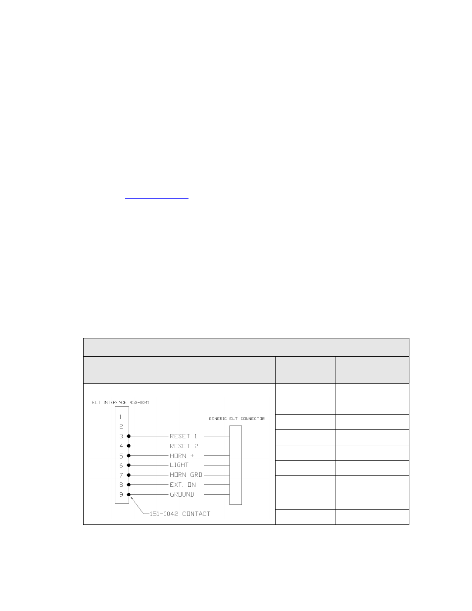
Table 3: ELT Wiring
PIN LOCATION
453-0041
INTERFACE
PIN #
GENERIC ELT
SIGNAL
DESCRIPTION
1
N/A
2
N/A
3
Reset 1
4
Reset 2
5
Horn +
6
Light
7
Horn Ground
(Aircraft Ground)
8
External ON
9
Aircraft Ground