12 jp2 – Acnodes PC 9150 User Manual
Page 23
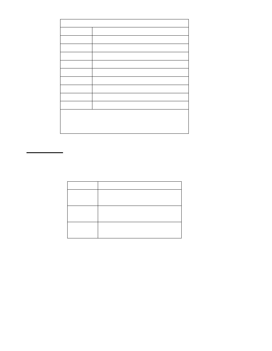
RS485 (option):
Pin#
Signal Name
1
NC
2
NC
3
485-
4
485+
5
Ground
6
NC
7
NC
8
NC
9
NC
BIOS Setup
Advanced/W 83627UHG Super IO
Conf iguration/Serial Port 1 Configuration RS-485
12 JP2:
(2.0mm Pitch 2x3 Pin Header),COM2 jumper setting, pin 1~6 are used to select s ignal
out of pin 9 of COM2 port.
JP2 Pin#
Function
Close 1-2
COM1 RI (Ring Indicator)
(default)
Close 3-4
COM1 Pin9=+5V
(option)
Close 5-6
COM1 Pin9=+12V
(option)
See also other documents in the category Acnodes Computers:
- RMC 7182 (103 pages)
- PC 6170 (75 pages)
- PC6172 (66 pages)
- RMC 7132 (98 pages)
- RMC 7155 (5 pages)
- RMC 7150 (66 pages)
- PC 6152 (77 pages)
- PCH 5120 (82 pages)
- PC 8150 (72 pages)
- RMC 7130 (8 pages)
- RMC 7130 (99 pages)
- PC 8120 (51 pages)
- PC 8120 (7 pages)
- KD 6176 (3 pages)
- RMC 7155 (67 pages)
- FPC-8057 (57 pages)
- FPC 6084 (105 pages)
- FPC 7150 (80 pages)
- FES 6831 (50 pages)
- FES 5312 (117 pages)
- PCH 3982 (87 pages)
- PCH 7591 (99 pages)
- PC 5153 (97 pages)
- FPC 7919 (104 pages)
- FPC 5105 (47 pages)
- FPC 6120 (114 pages)
- FPC 7615 (88 pages)
- PCH 7791 (99 pages)
- FES 2213 (57 pages)
- FES 2236 (49 pages)
- PCH 7991 (99 pages)
- PC 6408 (98 pages)
- FPC 7617 (88 pages)
- FPC 1015 (13 pages)
- FES 7510 (107 pages)
- PCH 3598 (82 pages)
- FPC 7161 (40 pages)
- PC 6172 (48 pages)
- PC 8153 (46 pages)
- FES 8730 (71 pages)
- PC 5192 (104 pages)
- PCH 3991 (77 pages)
- FES 6911 (58 pages)
- FES 2215 (37 pages)
- PC 6412 (107 pages)