Usb3, Jcom, Gpio – Acnodes PCH 3582 User Manual
Page 18
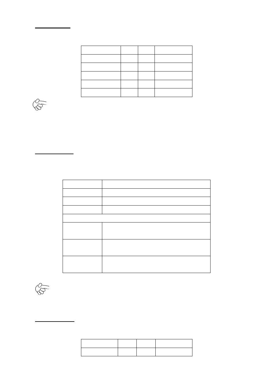
8. USB3:
(2.0mm Pitch 2x5 Pin Header) ,Front USB connector, it provides two USB
ports via a dedicated USB cable, speed up to 480Mb/s.
Signal Name
Pin# Pin# Signal Name
+5V
1
2
+5V
USB_P6_DN
3
4
USB_P7_DN
USB_P6_DP
5
6
USB_P7_DP
Ground
7
8
Ground
NC
9
10
Ground
Note:
Before connection, make sure that pinout of the USB Cable is in accordance with that
of the said tables. Any inconformity may cause system down and even hardware
damages.
9. JCOM:
(2.0mm Pitch 2x6 Pin Header) COM1 and COM3 setting jumper, pin 1~6 are
used to select signal out of pin 9 of COM1 port; pin 7~12 are used to select output type
for COM3 port (RS232 Type or RS422 Type or RS485 Type).
JCOM Pin#
Function
CLOSE 1-2
COM1 Pin9=RI
(default)
CLOSE 3-4
COM1 Pin9=+5V (option)
CLOSE 5-6
COM1 Pin9=+12V (option)
CLOSE 7-9
COM3 FOR
RS232 FROM
COM3
(default)
CLOSE 8-10
COM3 FOR RS485 FROM COM33
(option)
CLOSE 10-12 COM3 FOR RS422 FROM COM33
(option)
Note:
Since COM3 and COM33 use the same address, they cannot work at the same time.
10. GPIO:
(2.0mm Pitch 2x5 Pin Header),General-purpose input/output port, it provides
a group of self-programming interfaces to customers for flexible use.
Signal Name Pin#
Pin# Signal Name
GPIO20
1
2
GPIO60