2 jumpers setting and connectors, Jclr_cmos, Jvccio – Acnodes PCH 3582 User Manual
Page 16: Jcom6
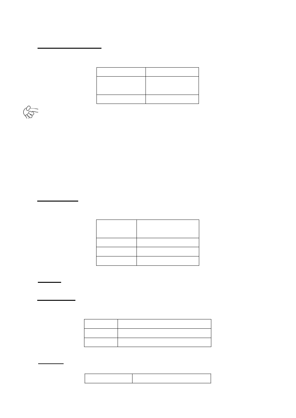
2.2 Jumpers Setting and Connectors
1. JCLR_CMOS:
(2.0mm Pitch 1x3 Pin Header)CMOS clear jumper, CMOS clear
operation will permanently reset old BIOS settings to factory defaults.
JCLR_CMOS
CMOS
CLOSE 1-2
NORMAL
(default)
CLOSE 2-3
Clear CMOS
Procedures of CMOS clear:
5.4.1.1 Turn off the system and unplug the power cord from the power outlet.
5.4.1.2 To clear the CMOS settings, use the jumper cap to close pins 2 and 3 for about
3 seconds then reinstall the jumper clip back to pins 1 and 2.
5.4.1.3 Power on the system again.
5.4.1.4 When entering the POST screen, press the key to enter CMOS
Setup Utility to load optimal defaults.
5.4.1.5 After the above operations, save changes and exit BIOS Setup.
2. JVCCIO:
(2.0mm Pitch 1x3 Pin Header) PC104+ port voltage selection jumper,select
voltage for PCI-104 Plus device.
The default for th
is jumper is “all open”,meaning
the user must select the voltage to be used.
JVCCIO
PC104+
VCCIO
Voltage
CLOSE 1-2
+3.3V
CLOSE 2-3
+5V
all Open
(Default)
3. BZ:
onboard buzzer.
4. JCOM6:
(2.0mm Pitch 1x3 Pin Header) COM6 setting jumper, pin 1~3 are used to
select signal out of pin 10 of COM6 port.
JP1 Pin#
Function
Close 1-2
COM6 Pin10=+5V (default)
Close 2-3
COM6 Pin10=+12V (option)
5. JP2:
(2.0mm Pitch 1X2 Pin Header), ATX Power and Power auto on setting jumper.
JP2
Mode