Push, Operation guide -4, Product layout & functions – Acclaim Lighting AL Driver 8-RGBW 24V User Manual
Page 6: Dmx address setting-dmx control mode, Rear panel layout, Front panel layout, Appendix
OUTPUT: 6A/CH.
DMX OUT
DMX IN
STAND ALONE
/ SLAVE
ON
OFF
MODE
V+
Red
Green
Blue
White
V+
Red
Green
Blue
White
V+
Red
Green
Blue
White
V+
Red
Green
Blue
White
V+
Red
Green
Blue
White
V+
Red
Green
Blue
White
V+
Red
Green
Blue
White
V+
Red
Green
Blue
White
2
4
6
8
1
3
5
7
1=Ground
2=Data-
3=Data+
RS
ON
10 1112
9
8
7
6
5
4
3
2
1
PUSH
PUSH
PUSH
1
1
1
2
2
2
3
3
3
3
3
3
2
2
2
1
1
1
DMX is short for Digital Multiplex. This is a universal binary language used as a form of
communication between intelligent fixtures. Each dip switch represents a binary value.
5.Operation Guide
-4-
In this mode, the dip-switch 10 is flipped to the "
" position. And this switch sometimes
used to activate a fixture special functions.
ON
Dip Switch 1 address equals 1
Dip Switch 2 address equals 2
Dip Switch 3 address equals 4
Dip Switch 4 address equals 8
Dip Switch 5 address equals 16
Dip Switch 6 address equals 32
Dip Switch 7 address equals 64
Dip Switch 8 address equals 128
Dip Switch 9 address equals 256
5.1. DMX Address Setting-DMX Control Mode
1,2,4
3,4
1,3,4
2,3,4
1,2,3,4
1,2,3,4,5,6,7,8,9
1
2
1,2
3
1,3
2,3
1,2,3
4
1,4
2,4
DMX ADDRESS (SLAVE)
SWITCHES ON
SWITCHES ON
(Dip Switch 10 = on)
START
CH#
START
CH#
1
2
3
4
5
6
7
8
9
10
11
12
13
14
15
..
511
..
..
..
..
..
..
..
1 2
3
4
5
6
7
8
9 10 11 12
ON
RS
ON
OFF
1 =
0=
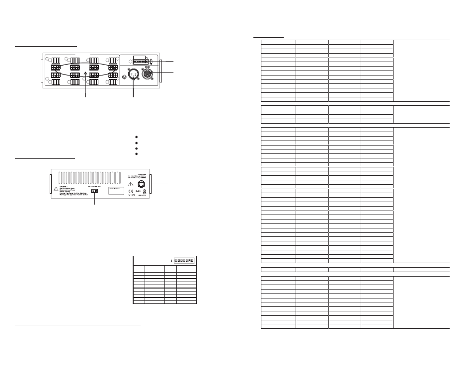
4.Product Layout & Functions
Hint
FULL ON
: When DMX address is "0", the output is
.
4.2. Rear Panel Layout
5. Power Input: 110-120VAC(3.2A)/220-240VAC(1.6A), 50/60Hz.
6. Voltage Selector: To select AC120V or AC230V by sliding the selector.
1. Dip Switch: Assign 12 dip-switches to set some function modes for user's desired effects.
2. DMX Input: 3-Pin XLR connector. Connect a universal DMX controller into this input for
receiving DMX values or DMX signals.
3. DMX Output: 3-Pin XLR connector. Connect to next DMX fixtures for sending DMX
values or DMX signals.
4. Output(Option): 8 terminal outputs, available in;
4.1. Front Panel Layout
5
6
1
3
2
4
12VDC, 6A/CH Total 12A Max.
15VDC, 6A/CH Total 10A Max.
18VDC, 6A/CH Total 8A Max.
24VDC, 6A/CH Total 6A Max.
119
0
46
100
120
0
43
100
121
0
40
100
122
0
37
100
123
0
34
100
124
0
31
100
125
0
28
100
126
0
25
100
127
0
22
100
128
0
19
100
129
0
16
100
130
0
13
100
131
0
10
100
132
0
7
100
Blue @ Full
Proportional Green
133
0
0
100
134
0
0
100
135
0
0
100
136
0
0
100
Blue @ Full only
137
3
0
100
138
6
0
100
139
9
0
100
140
12
0
100
141
15
0
100
142
18
0
100
143
21
0
100
144
24
0
100
145
27
0
100
146
30
0
100
147
33
0
100
148
36
0
100
149
39
0
100
150
42
0
100
151
45
0
100
152
48
0
100
153
51
0
100
154
54
0
100
155
57
0
100
156
60
0
100
157
63
0
100
158
66
0
100
159
69
0
100
160
72
0
100
161
75
0
100
162
78
0
100
163
81
0
100
164
84
0
100
165
87
0
100
166
90
0
100
167
93
0
100
Blue @ Full
Proportional Red
168
100
0
100
Red & Blue @ Full(PURPLE)
169
100
0
97
170
100
0
94
171
100
0
91
172
100
0
88
173
100
0
85
174
100
0
82
175
100
0
79
176
100
0
76
177
100
0
73
178
100
0
70
179
100
0
67
180
100
0
64
Red @ Full
Proportional Blue
6.Appendix
-9-