40 °c, Installation instructions, 5 adjsutment – STIEBEL ELTRON RTF Z 24.06.2003 - 19.12.2004 User Manual
Page 7: Display setting, Maximum floor temperature, Minimum floor temperature
7
English
M
+
–
OK
8968.01
28,5
81,5
81,5
44,5
8970.01
7
10
8
8969.01
47
9
F F
LH
L
N
Elektronik
RTF-Z
L
N
2. Installation instructions
for the qualified installer
All electrical connection and installation work
must be carried out in accordance with the
VDE (Association of German Electrical
Engineers) instructions (DIN VDE 0100 T520
A3), the regulations of the responsible
electricity supply companies, and the relevant
national and regional regulations.
Installation of the switch box in rooms with a
bath and/or a shower only outside zones of
protection 1 and 2.
In the event of interruption or a short circuit
of the probe line, the heating is switched off.
In the event of a defect the probe
line may carry mains voltage!
2.1 Installing the temperature probe
Prior to fitting the top covering of the floor, the
temperature probe is to be let into an empty
tube flush with the surface in the foundation
flooring (for example the screed flooring);
see operating and installation instructions for
temperature controlled floor mat.
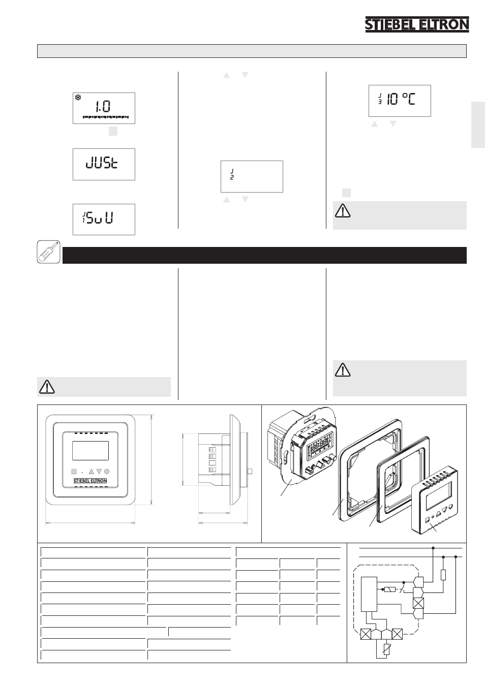
2.2 Installing the thermostat
The thermostat is to be inserted into a
standard commercial UP switch box for unit
diameters of 55 mm.
The thermostat is to be inserted as follows:
– Pull off the complete changeable frame (7-
9), to do this grasp the switch frame at the
top and bottom;
– Carry out the electrical connection in
accordance with the connection diagram
illustrated below or the printed instructions
on the back of the thermostat cover;
– Insert the thermostat (10) into the switch
box and screw together;
– Replace the casing cover (7), the inter-
mediate frame (8) and, if appropriate, the
switch frame (9) in addition.
The installation and operating
instructions for the floor heating unit,
to which the room thermostat should be
connected, are to be observed.
Length of temperature probe (DIN 44574)
4 m
Switching capacity
~ 12(2) A 230 V
Type
RTF-Z
Range of adjustment
ca. 10 ºC . . . 50 ºC
Protection class
ΙΙ
Switching difference
1 K
H x W x D
81,5 x 81,5 x 44,5 mm
Protection mode
IP 30
Power reserve
4 days, after 1h of operation
Sensor characteristics value
Temperature R [kOhm] U [V]
20 °C
2,43
2,22
10 °C
3,66
2,49
40 °C
1,15
1,63
30 °C
1,65
1,92
50 °C
0,82
1,35
1.5 Adjsutment
(can only be set in frost protection mode)
Individual settings of operating parameters, which remain stored even in the event of a power failure.
⇒
Select the frost protection ! operating
mode;
1
6
12
18
24
0
⇒
Simultaneously press M and OK for 3
seconds, until „Just“ is displayed;
Display setting
⇒
Press the
+
or
–
push-button to select
the type of display
S
= setpoint value
U
= time
SuU = setpoint value and time
alternating every 5 seconds;
⇒
Press the OK push-button to confirm and
switch to the next adjustment setting.
Maximum floor temperature
40 °c
⇒
Press the
+
or
–
push-button to set the
maximum adjustable floor temperature;
⇒
Press the OK push-button to confirm and
switch to the next adjsutment setting.
Minimum floor temperature
⇒
Press the
+
or
–
push-button to set the
minimum adjustable floor temperature
(difference between the minimum and
maximum floor temperatures at least
5 °C, if this figure is fallen short of the
maximum value is automatically adjusted);
⇒
Press the OK push-button to return to
the display setting or press push-button
M to terminate the adjustment mode.
The minimum floor temperature
does not have any affect on the
„Frost protection“ operating mode.
Approvals
see rating plate