Xantrex Technology ACCB-L User Manual
Page 40
Installation
2–18
973-0031-01-01 Rev A
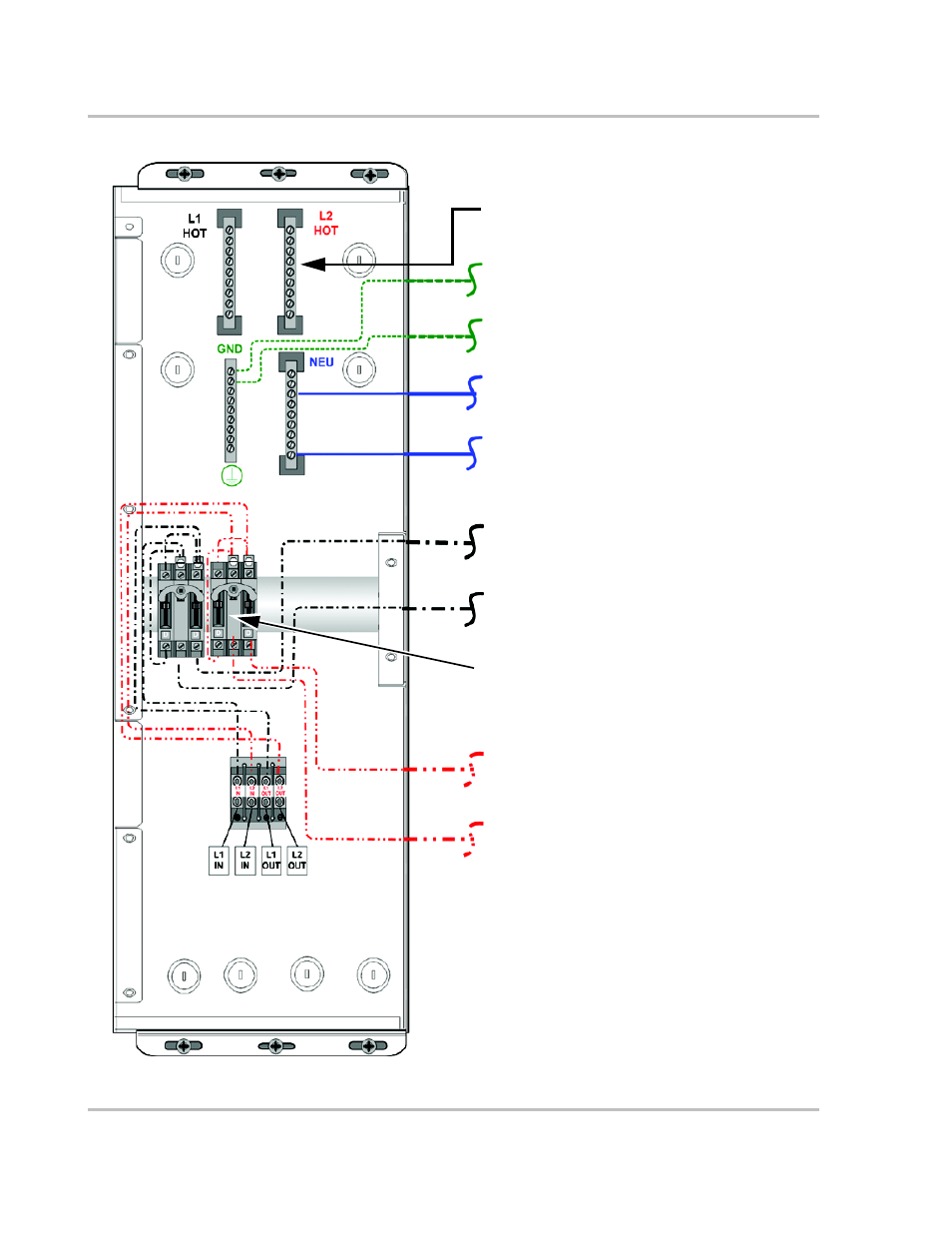
Figure 2-13 ACCB-L-L1 Internal Components with the Optional ACCB-L2-PKG Installed
ACCB-L2-PCK - Field-installed
AC Bypass Switch Assembly (for Inverter #2) (L2)*
Optional Field-installed, AC Bus Bar (L2 H
OT
)
Field-installed G
ROUND
Wire - Connects to the SW
Plus Inverter #2 G
ROUND
bar*
Field-installed N
EUTRAL
Wire - Connects to SW
Plus Inverter #2 NEU1 terminal*
Field-installed H
OT
Wire - Connects to SW Plus
Inverter #2 INV OUT terminal*
Field-installed H
OT
Wire - Connects to SW Plus
Inverter #2 AC1 GRID or AC2 GEN terminal*
*Provided with the ACCB-L2-PCK
Factory-installed G
ROUND
Wire - Connects to the
SW Plus Inverter #1 G
ROUND
Bar
Factory-installed N
EUTRAL
Wire - Connects to the
SW Plus Inverter #1 NEU1 terminal
Factory-installed H
OT
I
N
Wire - Connects to the SW
Plus Inverter #1 INV OUT terminal
Factory-installed H
OT
O
UT
Wire - Connects to the
SW Plus Inverter #1 AC1 GRID or AC2 GEN
terminal
IMPORTANT: This configuration is created by field-
installing an ACCB-L2-PCK into an ACCB-L1. This
configuration is not available, fully assembled, from the
factory.