York YMA024 User Manual
Page 2
036-21570-002 Rev. D (0605)
2
Unitary Products Group
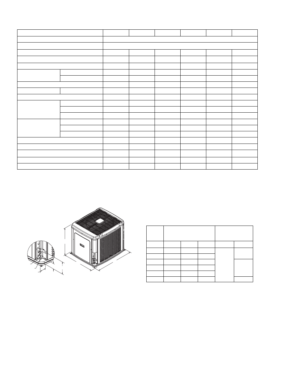
All dimensions are in inches. They are subject to change
without notice. Certified dimensions will be provided upon
request.
*
Expander fitting required for 1-1/8” line set.
Physical and Electrical Data
MODEL
YMA02411
YMA03011
YMA03611
YMA04211
YMA04811
YMA06011
Unit Supply Voltage
208-230V, 1
φ, 60Hz
Normal Voltage Range
1
187 to 252
Minimum Circuit Ampacity
14.3
18.1
21.9
32.6
34.7
39.0
Max. Overcurrent Device Amps
2
25
30
35
50
60
60
Compressor Type
Recip
Recip
Recip
Scroll
Scroll
Scroll
Compressor Amps
Rated Load
11.1
13.3
16.4
24.9
26.6
30
Locked Rotor
60
68
78
115
150
150
Crankcase Heater
Yes
Yes
Yes
No
No
No
Fan Motor Amps
Rated Load
0.5
1.5
1.5
1.5
1.5
1.5
Fan Diameter Inches
22
22
22
22
22
22
Fan Motor
Rated HP
1/15
1/4
1/4
1/4
1/4
1/4
Nominal RPM
850
850
850
850
850
850
Nominal CFM
2,300
3,500
3,500
3,850
3,500
3,300
Coil
Face Area (Sq. Ft.)
14.86
17.15
20.58
20.58
20.58
20.58
Rows Deep
1
1
1
1
1
2
Fins / Inch
22
22
22
22
22
22
Liquid Line Set OD (Field Installed)
3/8
3/8
3/8
3/8
3/8
3/8
Vapor Line Set OD (Field Installed)
3/4
3/4
7/8
7/8
7/8
1-1/8
Unit Charge (Lbs. - Oz.)
3
7 - 2
7 - 12
8 - 6
8 - 12
9 - 1
14 - 2
Charge Per Foot (Oz.)
0.68
0.68
0.70
0.70
0.70
0.78
Operating Weight (Lbs.)
175
220
225
225
245
285
1
Rated in accordance with ARI Standard 110, utilization range “A”.
2
Dual element fuses or HACR circuit breaker.
3
The Unit Charge is correct for the outdoor unit, matched indoor coil, and 15 feet of refrigerant tubing. For tubing lengths other than
15 feet, add or subtract the amount of refrigerant, using the difference in length multiplied by the per foot value.
VAPOR
LIQUID
2-3/8
3-1/8
6-1/2
C
A
B
DIMENSIONS
Unit
Model
Dimensions
(Inches)
Refrigerant
Connection
Service Valve Size
A
B
C
Liquid
Vapor
024
29-1/2
37
31
3/8”
3/4”
030
33-1/2
37
31
036
39-1/2
37
31
7/8”
042
39-1/2
37
31
048
39-1/2
37
31
060
39-1/2
37
31
7/8” *