Hardware connections, Front panel, Front panel leds – ZyXEL Communications P841C User Manual
Page 13: Back panel, Chapter 2 hardware connections, 1 front panel, 2 back panel, 1 front panel leds
P841C Central-Side VDSL Modem
Hardware Connections
2-1
This chapter gives a brief introduction to the P841C hardware.
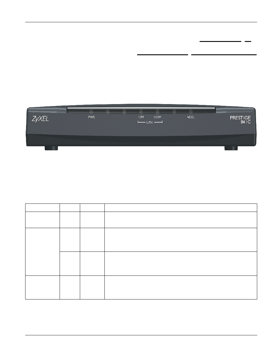
2.1 Front Panel
The following figure shows the front panel of the P841C.
Figure 2-1 P841C Front Panel
2.1.1 Front Panel LEDs
The following table describes the LED indicators on the front panel of the P841C.
Table 2-1 P841C LED Descriptions
LED COLOR
STATUS
DESCRIPTION
PWR Green
ON
OFF
The system is turned on.
The system is off.
LAN 10 M
Green
Blinking
ON
OFF
The system is transmitting/receiving to/from a 10 Mbps Ethernet network.
The link to a 10 Mbps Ethernet network is up.
The link to a 10 Mbps Ethernet network is down.
LAN 100 M
Yellow
Blinking
ON
OFF
The system is transmitting/receiving to/from a 100 Mbps Ethernet network.
The link to a 100 Mbps Ethernet network is up.
The link to a 100 Mbps Ethernet network is down.
VDSL Green
Blinking
ON
OFF
The system is transmitting/receiving to/from the VDSL modem.
The link to the VDSL modem is up.
The link to the VDSL modem is down.
2.2 Back Panel
The following figure shows the back panel of the P841C.
Chapter 2
Hardware Connections