System neutral requirements, Utility side isolation transformer requirements – Xantrex Technology PV225S-480-P User Manual
Page 61
Wiring - General
152606
3–13
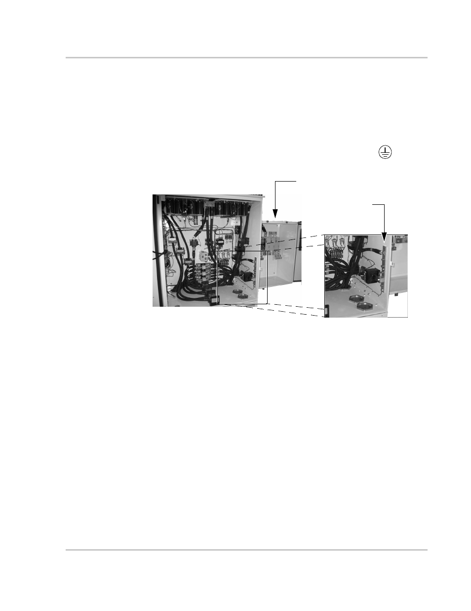
Chassis Ground
The chassis ground is a copper bus bar in the Main Inverter Enclosure and has
3/8-16" bolts for terminating the AC ground. The ground conductor size depends
on the size of the main circuit breaker.
NEC Table 250.122 (Ninth Edition) requires that the ground conductor be at least
#3 AWG for a 400 A circuit breaker.
Torque connections to ground bar in the Main Inverter Enclosure to
420 in-lb (47.5 Nm).
The equipment ground on the PV225S is marked with this symbol:
Array Grounding
NEC Article 690-41/42 (Ninth Edition) requires the PV array to be earth
grounded.
The PV225S chassis is also bonded to the PV safety ground terminal
block.
System Neutral Requirements
The PV225S is designed to be installed as a 4-wire system. As required by the
UL 1741 listing, a neutral conductor from the utility-interconnect must be
terminated at TB11 within the AC Interface Enclosure to ensure that the
AC voltage sensing circuit can perform an individual phase voltage
(line-to-neutral) measurement. The function of the neutral connection is to
provide a point of reference for measurement purposes that is essentially at
ground potential. No power will flow through the neutral conductor.
Utility Side Isolation Transformer Requirements
The PV225S is supplied with a a high efficiency custom Wye:Wye isolation
transformer as part of the AC interface/transformer assembly. The utility side
windings of the isolation transformer are configured Wye and must match the
voltage at the utility inter-tie. The PV225S is a balanced, three-phase,
Figure 3-11 Chassis Ground Bar (TB1)
Main Inverter Enclosure
AC Ground Bar (TB1)
to be used for the
Chassis Ground
DC Interface Enclosure